SINEAX V620 ENGLISH 1/4 SINEAX V620 ENGLISH 2/4 SINEAX V620 ENGLISH 3/4
Universal Signal Converter
• Universal input: voltage, current, thermocouples, thermoresistences, potentio-
• Sensor powered by 2-wire technique: 20 V DC stabilised, 20 mA max. with
short-circuit protection.
• Measurement and re-transmission on isolated analog output, with voltage and
• DIP-switch for selecting: type of input, START-END, output mode (zero eleva-
tion, scale inversion), output voltage type (mA or V).
• Front panel indicating: power on, off scale or setting error, alarm status.
• Relay (spst) output, programmable through PC.
• STROBE input to activate the analog output on PLC command (alternatively to
• Facility for programming the following with a PC: beginning and end scale, ad-
ditional input types, square root extraction, fi lter, burn-out etc.
• 3-point insulation: 1500 V AC.
10…40 V DC, 19…28 V AC, 50…60 Hz, max. 2.5 W; 1.6 W
at 24 V DC with 20 mA output
Bipolar from 75 mV up to 20 V in 9 scales,
input impedance 1 MΩ, resolution max. 15 bits + sign
Bipolar up to 20 mA, input impedance 50 Ω,
2, 3 or 4 wires measurement, energising current 0.56 mA,
resolution 0.1 °C, automatic detection of cable interruption or
RTD. Resistive value for NTC: < 25 kΩ.
KTY81, KTY84 and NTC may be set only via software
Type J, K, R, S, T, B, E, N; resolution 2.5 μV, automatic detection of
TC interruption, input impedance >5 MΩ
Rheostat input Full scale min. 500 Ω, max. 25 kΩ
Excitation voltage 300 mV, input impedance > 5 MΩ,
potentiometer value from 500 Ω to 100 kΩ (with the aid of a
parallel resistence equal to 500 Ω)
Variable from 240 sps with 11 bits resolution + sign to
15 sps with 15 bits + sign resolution (typical values))
35 ms with 11 bits resolution, 140 ms with 16 bits resolution
(measurement of voltage, current, potentiometer)
I: 0…20/4…20 mA, max. load resistance 600 Ω
V: 0…5/0…10/1…5/2…10 V, min. load resistance 2 kΩ
Resolution 2.5 μA / 1.25 mV
Relay output (spst) Capacity: 1 A … 30 V DC / V AC
Temperature: -20…60 °C, humidity min. 30%, max. 90%
at 40 °C non condensing (see «Installation instructions»)
Input for voltage/current 0.3%
Input for PTCs J, K, E, T, N 0.5% 0.2 °C
+(2) EMI: <1%Input for PTCs R, S 0.5% 0.5 °C
Input for PTC B (4) 0.5% 1.5 °C
Cold junction compensation 2 °C in ambient range 0 to 50 °C
Potentiometer/resistor 0.3%
Voltage output (3) 0.3% 0.01%
Data memory EEPROM for all confi guration data; storage time: 40 years
EN 61000-6-4/2007 (electromagnetic emission, industrial environment)
EN 61000-6-2/2005 (electromagnetic immunity, industrial environment)
All circuits are to be safety isolated from hazardous live by double insulation. The power supply
transformer must comply with EN 60742: Isolating transformers and safety isolating transfor-
– Use with copper conductor
– Use in pollution degree 2 environment
– Power supply must be Class 2
– When supplied by an isolated limited voltage/limited current power supply a fuse rated
max. 2.5 A shall be installed in the fi eld.
(1) Infl uence of cable resistance 0.005%/Ω, max. 20 Ω
(2) Infl uence of cable resistance 0.1 μV/Ω
(3) Values to be added to the errors of the selected input
(4) Output zero if t < 400 °C
(5) All the values have to be calculated on the resistive value
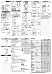
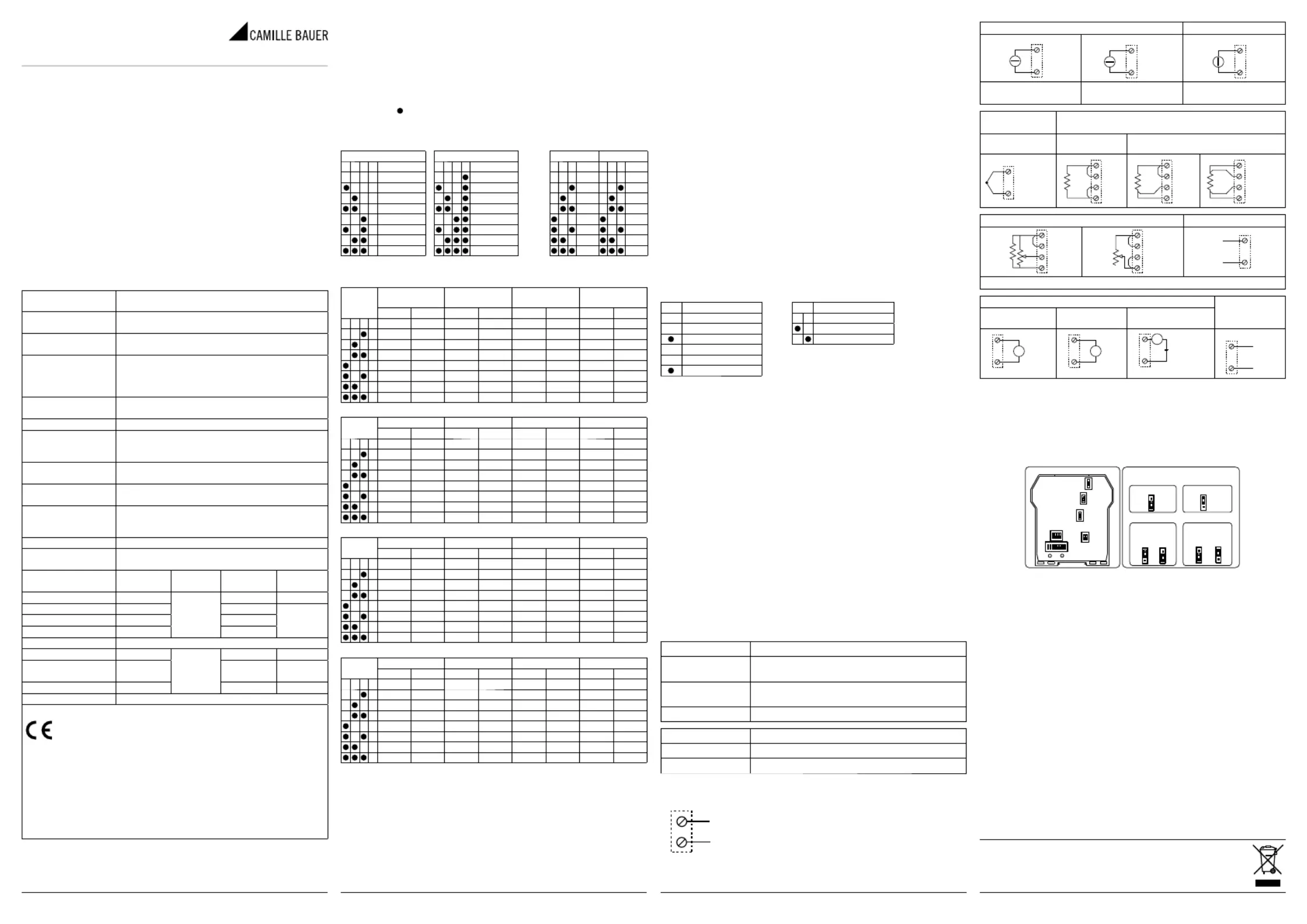
Selection input / measuring scale
The type of input is selected by setting the SW1 DIP-switch group at the side
Every type of input is matched to a certain number of scale beginnings and ends
values which can be selected with the SW2 group.
The table below lists possible START and END values according to the type of
Note for all following tables:
The indication indicates that the DIP-switch is set in position ON.
No indication is provided when the DIP-switch is set in position OFF!
SW1: INPUT TYPE SW2: START and END
Input type Input type START END
START END START END START END START END
1 (*) (*) (*) (*) (*) (*) (*) (*)
2 0 V 100 mV 0 Ω 1 kΩ 0 mA 1 mA 0% 40%
3 400 mV 200 mV 0.5 kΩ 2 kΩ 1 mA 2 mA 10% 50%
4 1 V 500 mV 1 kΩ 3 kΩ 4 mA 3 mA 20% 60%
5 2 V 1 V 2 kΩ 5 kΩ -1 mA 4 mA 30% 70%
6 -5 V 5 V 5 kΩ 10 kΩ -5 mA 5 mA 40% 80%
7 -10 V 10 V 10 kΩ 15 kΩ -10 mA 10 mA 50% 90%
8 -20 V 20 V 15 kΩ 25 kΩ -20 mA 20 mA 60% 100%
Ni100 (RTD) PT100 (RTD) PT500 (RTD) PT1000 (RTD)
START END START END START END START END
1 (*) (*) (*) (*) (*) (*) (*) (*)
2 -50 °C 20 °C -200 °C 50 °C -200 °C 0 °C -200 °C 0 °C
3 -30 °C 40 °C -100 °C 100 °C -100 °C 50 °C -100 °C 50 °C
4 -20 °C 50 °C -50 °C 200 °C -50 °C 100 °C -50 °C 100 °C
5 0 °C 80 °C 0 °C 300 °C 0 °C 150 °C 0 °C 150 °C
6 20 °C 100 °C 50 °C 400 °C 50 °C 200 °C 50 °C 200 °C
7 30 °C 150 °C 100 °C 500 °C 100 °C 300 °C 100 °C 300 °C
8 50 °C 200 °C 200 °C 600 °C 150 °C 400 °C 200 °C 400 °C
Thermocouple J Thermocouple K Thermocouple R Thermocouple S
START END START END START END START END
1 (*) (*) (*) (*) (*) (*) (*) (*)
2 -200 °C 100 °C -200 °C 200 °C 0 °C 400 °C 0 °C 400 °C
3 -100 °C 200 °C -100 °C 400 °C 100 °C 600 °C 100 °C 600 °C
4 0 °C 300 °C 0 °C 600 °C 200 °C 800 °C 200 °C 800 °C
5 100 °C 400 °C 100 °C 800 °C 300 °C 1000 °C 300 °C 1000 °C
6 200 °C 500 °C 200 °C 1000 °C 400 °C 1200 °C 400 °C 1200 °C
7 300 °C 800 °C 300 °C 1200 °C 600 °C 1400 °C 600 °C 1400 °C
8 500 °C 1000 °C 500 °C 1300 °C 800 °C 1750 °C 800 °C 1750 °C
Thermocouple T Thermocouple B Thermocouple E Thermocouple N
START END START END START END START END
1 (*) (*) (*) (*) (*) (*) (*) (*)
2 -200 °C 50 °C 0 °C 500 °C -200 °C 50 °C -200 °C 200 °C
3 -100 °C 100 °C 500 °C 600 °C -100 °C 100 °C -100 °C 400 °C
4 -50 °C 150 °C 600 °C 800 °C 0 °C 200 °C 0 °C 600 °C
5 0 °C 200 °C 700 °C 1000 °C 100 °C 300 °C 100 °C 800 °C
6 50 °C 250 °C 800 °C 1200 °C 150 °C 400 °C 200 °C 1000 °C
7 100 °C 300 °C 1000 °C 1500 °C 200 °C 600 °C 300 °C 1200 °C
8 150 °C 400 °C 1200 °C 1800 °C 400 °C 800 °C 500 °C 1300 °C
(*) START or END are set in the memory with the PC or with the programming
N.B.: DIP-switches must be set while the module is powered down, other-
wise, the module may be damaged!
Setting START and END at will
The START and END push-buttons under the SW2 DIP-switch group allow to set
the beginning and end scale at will within the scale pre-set through the DIP-swit-
ches. To obtain this facility it is necessary to use a suitable signal generator, able
to furnish the desidered values of beginning and end scale.
The procedure is following:
1. Set through DIP-switches, the type of input, START and END measurement
which include the required beginning and end values.
3. Supply a calibrator or simulator of the signal you wish to measure and retrans-
4. Set the required START value on the calibrator (or other instrument).
5. Press the START push-button for at least 3 sec. The green LED on the front
panel fl ashes to indicate the value has been stored.
6. Repeat points 4 and 5 for the required END value.
7. Cut power to the module and set to OFF position the DIP-switches of group
SW2, correspondent to the settings of START and END values.
The module is now confi gured for the required start and end scale. To reprogram
it (e.g. for a different type of input) repeat the whole procedure.
DIP-switches numbers 7 and 8 of the SW2 group enable you to set the output
with or without zero elevation, or as a normal or reversed output. The SW3 DIP-
switch group enables you to select the output type.
N.B.: DIP-switches must be set while the module is powered down, avoiding
electrostatic discharges, otherwise the module may be damaged.
SW2 Output mode SW3 Output
By using a PC and V620/V622-C software, it is possible to set other normally
fi xed parameters in addition to start and end scale.
• Digital fi lter (normally disabled)
• Square root extraction (normally disabled)
• Negative burn-out (normally positive)
• Alarm (normally set as error signalling)
• Start and end scale of the analog output
• Value of the analog output in case of error
• Rejection programmable for 50 or 60 Hz mains frequency (normally set to
• Sampling frequency/resolution (normally set to 15 sps/16 bits)
• 3 or 4 wires measure for thermal resistance (normally set to 3 wires)
• Action of the digital output alarm in case of fault.
Instructions for setting and for the connection cable are supplied with the soft-
ware (to be requested as an accessory item).
LED indication on the front
Out range, burn-out or internal fault
Error on DIP-switches setting
Steady ON Indicates the presence of power supply
Steady ON Alarm signalling (relay contact opened)
OFF No alarm (relay contact closed)
Power supply voltage must be in the range 10 to
40 V DC (at any polarity), 19 to 28 V AC; also see
section “Installation instructions”.
The upper limits must not be exceeded, to
avoid serious damage to the module. Protect
the power supply source against possible damage of the module by using a fuse
Current input Voltage input
PT100, Ni100, PT500, PT1000
Potentiometer/rheostat input Strobe input (7)
With resistance R = 500 Ω (not provided), P = 500 Ω ÷ 100 kΩ
(7) As alternative to the relay output. It is isolated from the other circuits and
enables the current analog output. It may be used to multiplex a PLC input
on an V620. To enable it see “Settings through internal bridges”.
(8) Active output (powered) to connect to passive inputs.
(9) Unpowered passive output to be connected to active inputs. To enable it,
see “Settings through internal bridges”
(10) As alternative to STROBE input; relay contact normally closed, opened in
INTERNAL BRIDGES POSITION SETTINGS THROUGH INTERNAL BRIDGES
RELAY OUTPUT / STROBE INPUT
Installation instructions
The module was designed for fi tting to guide 46277, in a vertical position. For
optimum operation and long life, make sure adequate ventilation is provided for
the module/s, avoiding placing raceways or other objects which could obstruct
the ventilation grilles. Do not install the modules above appliances generating
heat we advise you to install in the lower part of the panel.
Severe operating conditions
Severe operating conditions are as follows:
• High power supply voltage (> 30 V DC / > 26 V AC).
• Power supply of the sensor at input.
• Use of the output on generated current.
When modules are installed side by side, it may by necessary to separate them
by at least 5 mm in the following cases:
• If panel temperature exceed 45 °C and at least one of the severe operating
• If panel temperature exceed 35 °C and at least two of the severe operating
We advise you to use shielded cables for connecting signals. The shield must
be connected to an earth wire used specifi cally for instrumentation. Moreover,
it is good practice to avoid routing conductors near power appliances such as
inverters, motors, induction ovens, etc.
Camille Bauer Metrawatt AG Fax +41 56 618 21 21
Aargauerstrasse 7 info@cbmag.com
CH-5610 Wohlen/Switzerland www.camillebauer.com