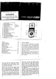
SINEAX VS30 - 162967
2-DRAHT - LOOP POWERED WANDLER FÜR PT100 UND NI100 SENSOREN
Allgemeine Beschreibung
Der VS30 wandelt ein Temperatursignal eines PT100 (EN 60 751) oder NI100 Sensors in
2-, 3- oder 4-Draht Technik in ein 4 - 20 mA Stromschleifensignal (2-Draht Technologie)
um.
Die Moduleigenschaften sind:
GERMAN - 1/8 GERMAN - 5/8 GERMAN - 7/8
GERMAN - 2/8 GERMAN - 6/8
GERMAN - 3/8
GERMAN - 4/8
D
Elektrische Verbindungen
8 mm
0,2..2,5 mm2
Das Modul besitzt Federklemmen für die elektrischen
Anschlüsse.
Nehmen Sie bei den Anschlüssen auf die folgenden
AnweisungenBezug:
1 Entfernen Sie 0,8 cmder Isolierung am Ende der
Kabel
2 Führen Sie einen Schraubenzieher in die
quadratische Öffnung ein und drücken Sie ihn, bis sich
die Feder öffnet, die das Kabel blockiert
3 Führen Sie das Kabel in die runde Öffnung ein
4 Ziehen Sie den Schraubenzieher heraus und
überprüfen Sie, ob das Kabel sicher in der Klemme
befestigt ist.
LED Indikatoren an der Front
LED Bedeutung
Schnelles Blinken
3 Impulse/Sek.
Interner Fehler
Langsam Blinken
1 Impuls/Sek. DIP-Schalter Einstellung Fehler (Skalierung oben und
Limit Startbereich)
Ständig an Sensoranbindung Drahtbruch.
Messung außerhalb Bereich, 3 Drahtwiderstand außerhalb.
rd
OVER RANGE (*)
8SW2
JA: ein 2.5% Over-range Wert ist akzeptiert;
ein 5% Over-range Wert stellt einen Fehler dar.
NEIN: Nur der Fehler verursacht einen 2.5% Over Range Wert.
Technische Eigenschaften
Messbereich:
Widerstandsbereich :
Minimale Steigung :
:
Leitungswiderstand:
Anschluss :
Auflösung :
Strom am Sensor
-200 - +650 °C
18,5 - 330
20 °C
750 A
Max 25
2-, 3- oder 4-Draht
6 m
Ω Ω
Ω pro Kabel
m
W
~
Pt100 Eingang-EN 60751/A2 (ITS-90)
Messbereich:
Widerstandsbereich :
Minimale Steigung :
:
Leitungswiderstand:
Anschluss :
Auflösung :
Strom am Sensor
-60 - +250 °C
69 - 290
20 °C
750 A
Max 25 pro Kabel
2-, 3- oder 4-Draht
6 m
Ω Ω
Ω
m
W
~
NI100 Eingang
5 30 V
4 - 20 mA, 20 - 4 mA (2-Draht Technologie)
1 k @ 26 V , 21 mA (siehe auf Seite 2,
Diagramm)
1 A (>14 Bit)
102,5% des oberen Bereichswerts (siehe Tabelle Seite 5)
105% des oberen Bereichswerts (siehe Tabelle Seite 5)
Inetwa 30 mA
- DC
DCΩLastwider-
standvs minimaleBetriebsspannung
m
Betriebsspannung :
Lastwiderstand :
Auflösung :
:
Ausgang bei Fehler :
Stromausgang Schutz:
Stromausgang :
Ausgangbei Over-range
Ausgang/Versorgung
1200
800
400
0
R =((U-5)/0.021)
Last
5 10 15 20 25 30
Minimale funktionierende Spannung U
Standards : EN61000-6-4/2002-10 elektromagnetische Emission,
ind strielle Umgebung
EN61000-6-2/2006-10
(
u )
(elektromagnetische Immunität,
industrielle Umgebung)
Betriebsbedingungen :
Lagertemperatur:
:
Anschlüsse :
Kabelquerschnitt:
LED Indikatoren
Abisolierung :
Gehäuse:
Abmessungen, Gewicht:
Temperatur -20 - +65 °C
Feuchtigkeit 30 - 90 % bei 40°C (nicht kondensierend)
Höhe: bis zu 2000 über NN
Einstellungsfehler,Verbindungsfehler,interner Fehler
Klemmenanschlüsse
(schwarze Farbe)
-40 - +85 °C
0,2 - 2,5 mm
8 mm
PBT
6,2 x 93,1 x 102,5 mm, 45 g
2
Diagramm: Lastwiderstand vs minimaleBetriebsspannung
Rlast ( )W
1 - Setzen Sie das Modul in den oberen
Teil der Schiene ein
2 - Drücken Sie das Modul nach unten
1 - Hebeln Sie mit einem Schraubenzieher
(wie auf der Abbildung gezeigt)
2 - Drehen Sie das Modul nach oben
Für spezifische Einstellungen des Moduls, werden die DIP-Schalter Positionen in den
nachfolgendenTabellen dargestellt.
Anmerkung:Für alle Tabellen
Die Beschriftung zeigt an, dass der DIP-Schalter in der ON Position ist.
KeinEintrag bedeutet, dass der DIP-Schalter inder Position ist.
Pt100 ANSCHLUSS
1
SW1
3 Draht Anbindung
2 / 4 Draht Anbindung
50 / 60 Hz STÖRFREQUENZUNTERDRÜCKUNG (*)
2
SW1
Vorhanden
Abwesend
(*) Der Filter verlangsamt die Antwortzeit um etwas 620 ms und garantiert die Wieder-
holung des Störsignals bei 50 / 60 Hz, die das Messsignal überlappt.
INVERTIERTER AUSGANG
3
SW1
Invertiert: 20 - 4 mA
Normal: 4 - 20 mA
Für eine bessere Belüftung des Moduls empfehlen wir die Montage in vertikaler Stellung
sowie die Vermeidung der Positionierung in Kanälen oder von sonstigen Gegenständen,
die eine Belüftung behindern.Vermeiden Sie die Installation des Moduls über Geräten, die
Wärme erzeugen; wir empfehlen die Installation im unteren Bereich der Schalttafel oder
des Gehäuses.
Pt100 Anschluss
Störunterdrückung
Invertierter Ausgang
Typ Pt100
Messbereich Start
MessbereichEnde
Ausgangssignal bei einem
Fehler
Over Range
3 Draht
Vorhanden
NEIN
PT100
0 °C
100 °C
In Richtung oberer Bereich der Ausgangsskalierung
2.5% Over-range Wert ist akzeptiert;
ein 5% Over-range Wert stellt einen Fehler dar.
JA: ein
MESSBEREICH START
6SW1 7 8 °C
0
-10
-20
-40
-50
-100
-150
-200
Pt100 TYP
4
SW1
PT100
NI100
NICHT VERWENDET
5SW1 Nicht verwendet
EINGANGSSIGNAL SKALIERUNG BEREICH
1 1SW2SW2 1SW22 2 23 3 34 4 45 5 56 6 6°C °C °C
0 120 340
5 130 350
10 140 360
15 150 370
20 160 380
25 170 390
30 180 400
35 190 410
40 200 420
45 210 430
50 220 440
55 230 450
60 240 480
65 250 500
70 260 520
75 270 550
80 280 580
85 290 600
90 300 620
95 310 650
100 320
110 330
(*) Siehe folgende Tabelle für die korrespondierenden Werte.
Signalausgang Limit Over range / Fehler ± ±2,5 % Fehler 5 %
20 mA 20,4 mA 21 mA
4 mA 3,6 mA < 3,4 mA
AUSGANGSSIGNAL BEI FEHLER
7SW2
In Richtung oberer Wert des Ausgangsbereichs
In Richtung unterer Wert des Ausgangsbereichs
Eingang
Das Modul akzeptiert Eingänge von einem Pt100 (EN 60 751) oder NI100
Temperatursensor über 2-, 3- oder 4-Draht Anbindung.
Die Verwendung von geschirmten Kabelnfür die Elektrische Verbindung wird empfohlen.
Die ist der Anschluss für kurze Entfernungen ( < 10 m) zwischen dem Modul und Sensor,
unter der Berücksichtigung eines addierenden Fehlers (welcher durch Software-
programmierung entfernt werden kann) äquivalent zu dem Leitungswiderstand der
Verbindungsleitungen.
DIP-Schalter SW1-1 ist in ON Position(2 / 4 Draht)oder alleDIP-Schalter in OFF Position
(Konfiguration vom Speicher:Modul programmiert über PC für 2-Draht Anbindung).
Mit Brücken zwischenKlemmen 1 und 2 und Klemmen 3 und 4.
Die ist der Anschluss für mittlere Entfernungen (> 10 m) zwischen dem Modul und Sensor.
Das Instrument führt eine Kompensation des Leitungswiderstandes für die
Anschlusskabel durch. Damit die Kompensation korrekt durchgeführt werden kann,
müssen wie Widerstandswerte aller Drähte gleich sein, da das Instrument nur einen
Drahtwiderstand misst und diesen für alle anderen Drähte annimmt.
DIP-Schalter SW1-1 in OFF Position (3-Draht) oder alle DIP-Schalter in OFF Position
(Konfiguration vom Speicher:Modul programmiert über PC für 3-Draht Anbindung.)
Mit Brücke zwischenKlemmen 3 und 4.
Die ist der Anschluss für längere Entfernungen (> 10 m) zwischen dem Modul und Sensor.
Stellt die höchste Genauigkeit zur Verfügung, da das Instrument den Sensorwiderstand
unabhängig vom Leitungswiderstand ermittelt.
DIP-Schalter SW1-1 in ON Position (2-/4-Draht) oder alle DIP-Schalter in OFF Position
(Konfiguration vom Speicher:Modul programmiert über PC für 4-Draht Anbindung.)
2-Draht Anbindung
3-Draht Anbindung
4-Draht Anbindung
15
6
7
8
2
3
4
AUSGANG
EINGANG
Ausgang
Anbindung Stromschleife (geregelter Strom).
Die Verwendung von geschirmten Kabelnfür die Elektrische Verbindung wird empfohlen.
Anmerkung: Um die Verlustleistung des Instruments so gering wie möglich zu halten,
empfehlen wir eine Last von > 250 am Stromausgang.
Ω
15
6 2
3
4
AUSGANG
EINGANG
+
-
U
Iout
RLoad
Entsorgung von alten Elektro und Elektronikgeräten (gültig in der Europäischen Union
und anderen europäischenLändern mitseparatem Sammelsystem)
Dieses Symbol auf dem Produkt oder auf der Verpackung bedeutet, dass dieses Produkt nicht
wie HausmuII behandelt werden darf. Stattdessen soll dieses Produkt zu dem geeigneten
Entsorgungspunkt zum Recyclen von Elektro und Elektronikgeräten gebracht werden. Wird das
Produkt korrekt entsorgt, helfen Sie mit, negativen Umwelteinflüssen und Gesundheitsschäden
vorzubeugen, die durch unsachgemäße Entsorgung verursacht werden könnten. Das Recycling
von Material wird unsere Naturressourcen erhalten. Für nähere Informationen über das
Recyclen dieses Produktes kontaktieren Sie bitte Ihr lokales Bürgerbüro, Ihren Hausmüll
Abholservice oder dasGeschäft, in dem Siedieses Produkt gekauft haben.
Other Features
50 Hz und 60 Hz (einstellbar)
Max of 0,1% (des Messbereichs) oder 0,1 °C
< 0,5 %
0,005 /
< 100 ppm,typisch : 30 ppm
100 ms (ohne
)
< 220 ms (ohne
< 620 ms )
W W
50/60 Hz Unterdrückung)
300 ms (mit 50/60 Hz Unterdrückung aktiviert
50/60 Hz Unterdrückung)
(ohne 50/60 Hz Unterdrückung aktiviert
IP20Schut klassez :
(*) EMI: Elektromagnetische Interferenzen.
Netzwerk Störfrequenzunterdr.:
:
Fehler durch EMI (*)
Antwortzeit (10 -90 %):
Übertragungsfehler
Temperaturkoeffizient :
Abtastrate:
Einfluss des Kabelwiderst. : Kundenspezifische Einstellungen
1
2
3
4
1
2
3
4
1
2
3
4
JJJ
GERMAN - 8/8
Die Konfiguration kann unabhängig von der DIP-Scjalterlage in den Speicher geschrieben
werden. Gespeicherte Parameter erhält man nur, wenn DIP-Schalter in OFF Position
Konfiguration über PC
%
%
%
%
%
%
%
%
%
Skalierung von Start und Ende
Pt100 Anbindung: 2-Draht, 3-Draht oder 4-Draht.
Störfreqquenzunterdrückung für 50 / 60 Hz Netzfrequenz: Vorhanden oder abwesend.
Messung Filter: Vorhandenoder nicht vorhanden (1,2 ,5 ,10, 30,60 Sekunden).
Ausgang:Normal (4 - 20 mA) oder invertiert (20 - 4 mA).
Pt100 Typ:Pt100 oder NI100.
Kabelwiderstand Kompensation für 2-Draht Messung
Ausgangssignal bei Fehler: In Richtung Anfang oder Ende des Ausgangsbereichs
Überlast: NEIN ( ) oder JA (Nur der Fehler verursacht einen 2.5% Überlast Wert Ein 2.5%
Überlast Wert ist akzeptabel ein 5% Überlast Wert wird als Fehler betrachtet.
Es ist ebenso möglich, die Skalierung des Ausgangsbereichs einzustellen.
Die Konfiguration über PC ist mit folgendem Zubehör möglich:
USB zu RS232 / TTL
Verbindungskabel zwischen CBConfig Box und VS30
Entsprechende Programmiersoftware
EINSTELLUNG ÜBER DIP-SCHALTER
Konfiguration über den Speicher (Werkseinstellung)
Das Modul wird mit allen DIP-Schaltern in OFF Position ausgeliefert.
In dieser Position verwendet das Modul die im Speicher abgelegten Einstellungen. Diese
Konfiguration kann über PC verändert werden (siehe Abschnitt
Die Werkseinstellung ist wie folgt (wenn keine anderen Indikationen am Instrument
vorhandensind):
Einstellung über PC ).
MODUL KONFIGURATION
Das Modul kann entweder über DIP-Schalter oder PC konfiguriert werden.
Konfiguration nicht benutzt (ist nicht modifiziert und wird genutzt, wenn alle DIP-Schalter
in OFF Position sind) und dementsprechend ist es erforderlich, dass alle Parameters
gemäß den nachfolgenden Tabellen eingestellt werden.
Wenn nur ein DIP-Schalter in OFF Position ist, dann wird die im Speicher abgelegte
Montage des Moduls in der Schiene Entfernung des Moduls von der Schiene
Anweisungen zur Installation
Das Modul ist für die Montage auf Schienen nach DIN 46277 ausgelegt.
%
%
%
%
%
%
%
Hohe Genauigkeit
Sehr schmales Gehäuse (6.2 mm)
35 mm Hut-Schiene
xxxxxSoftware.
16 Bit Auflösung
.
Befestigung auf
Konfigurierbar über PC mit
Konfiguration über DIP-Schalter
Schnelle Anbindung über Klemmenbefestigung
Das Modul kann auchprogrammiert werden, wenn die 4- 20 mASchleife nicht aktiv ist, da
die Versorgung über den Programmierstecker erfolgt.
Das Interface für die Modulprogrammierung befindet sichunter der Abdeckung.
Besitzt der Anwender das oben aufgelistete Zubehör, können die folgenden Parameter
programmiert werden:
15
6 2
Programmierung
SINEAX VS30
SINEAX VS30 SINEAX VS30 SINEAX VS30 SINEAX VS30
SINEAX VS30 SINEAX VS30 SINEAX VS30
MI001840-F/D
Camille Bauer AG
Aargauerstrasse 7
CH-5610 Wohlen/Switzerland
Phone +41 56 618 21 11
Fax +41 56 618 35 35
e-Mail: info@camillebauer.com
http://www.camillebauer.com