Hikvision DS-K5671-ZV Manual
Hikvision
Sikkerhed adgangskontrolsystem
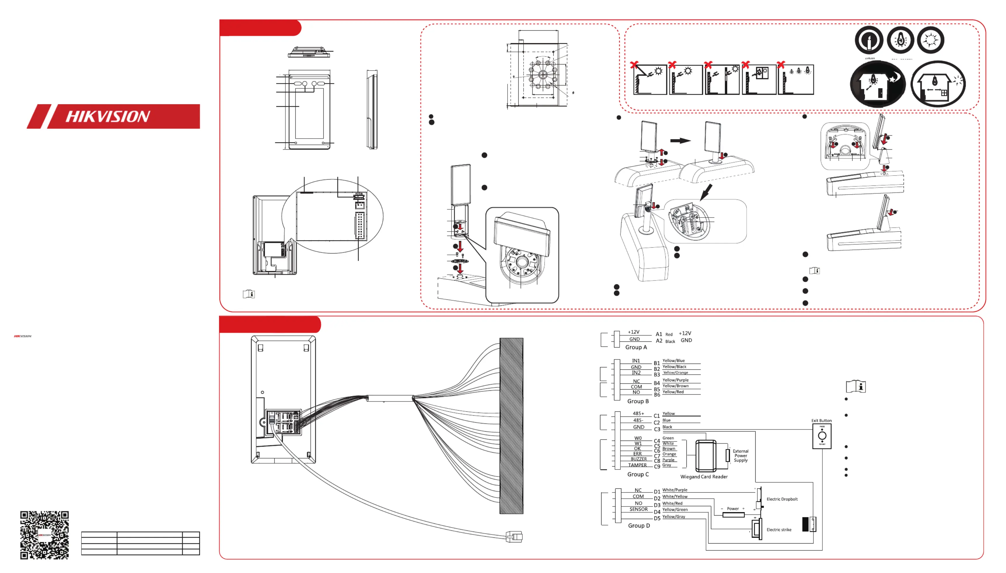
DS-K5671-ZV
| Mærke: | Hikvision |
| Kategori: | Sikkerhed adgangskontrolsystem |
| Model: | DS-K5671-ZV |
Har du brug for hjælp?
Hvis du har brug for hjælp til Hikvision DS-K5671-ZV stil et spørgsmål nedenfor, og andre brugere vil svare dig
Sikkerhed adgangskontrolsystem Hikvision Manualer
2 November 2025

1 November 2025

1 November 2025
30 Oktober 2025
7 Oktober 2025

1 Oktober 2025
1 Oktober 2025
1 Oktober 2025

4 August 2025
4 August 2025
Sikkerhed adgangskontrolsystem Manualer
- Marmitek
- Honeywell
- ACTi
- Geovision
- Bosch
- Abus
- Verkada
- Velleman
- UHPPOTE
- Techly
- Peerless-AV
- LiftMaster
- Paxton
- Eminent
- ZKTeco
Nyeste Sikkerhed adgangskontrolsystem Manualer

1 November 2025
31 Oktober 2025
31 Oktober 2025
30 Oktober 2025
27 Oktober 2025
26 Oktober 2025
26 Oktober 2025
19 Oktober 2025
13 Oktober 2025

7 Oktober 2025