Hinkley Lighting Jules 53241BN Manual

Hinkley Lighting Lys Jules 53241BN

Læs gratis den danske manual til Hinkley Lighting Jules 53241BN (2 sider) i kategorien Lys. Denne vejledning er vurderet som hjælpsom af 43 personer og har en gennemsnitlig bedømmelse på 4.5 stjerner ud af 22 anmeldelser. Har du et spørgsmål om Hinkley Lighting Jules 53241BN, eller vil du spørge andre brugere om produktet?

Side 1/2
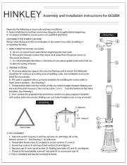
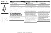
assembly instructions
Item No. 53241
1. Find a clear area in which you can work.
2. Unpack fixture and glass from carton.
3. Carefully review instructions prior to assembly.
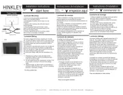
1. Prepare gem strap for mounting by threading two screws provided into (A) (B)
back of gull wing bracket of gem strap - see .(A) Drawing 1
Be sure the holes into which the screws are threaded match the spacing of holes (D)
in the canopy (G) - see .Drawings 1 and 2
2. Mount gem strap to junction box , using the two 8-32 screws (A) (J) (C) .(not provided)
Make electrical connections from supply wire to fixture lead wires. Refer to instruction
sheet and follow all instructions to make all necessary wiring connections. (I.S. 18)
Then refer back to this sheet to continue installation of this fixture.
1. Hang the fixture by slipping the mounting holes in the canopy over screws (B), (D) (1)
mounted in strap previously - see .(A) Drawing 2
2. Thread ball knobs onto end of screw and tighten to secrure fixture. (E) (B)
*** The construction of this fixture will be accomplished by first mounting the
mounting strap to the junction box, making all necessary electrical connections,
hanging the fixture from the ceiling, and then installing the glass.
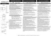
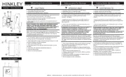
start here
53241
SAFETY WARNING: READ WIRING AND GROUNDING INSTRUCTIONS (I.S. 18)
AND ANY ADDITIONAL DIRECTIONS. TURN POWER SUPPLY OFF DURING
INSTALLATION. IF NEW WIRING IS REQUIRED, CONSULT A QUALIFIED
ELECTRICIAN OR LOCAL AUTHORITIES FOR CODE REQUIREMENTS.
Drawing 2 - Fixture Mounting
Drawing 3 - Glass Installation
Drawing 1 - Strap Detail
B
(side view)
gull wing
bracket
B
B
D
J
C
A
1
E
01.01.13
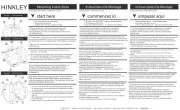
1. To install glass, slip tube over threaded stem on bottom of fixture body(1) (2)
- see .Drawing 3
2. Slip cap over threaded stem followed by ring and plastic washer .(3) (2) (4) (5)
3. Slip threaded stem through center hole of glass and hold glass in position.(2) (6)
4. Slip plastic washer followed by steel washer onto threaded stem and hold(7) (8) (2)
parts in position.
5. Thread hex nut onto threaded stem and tighten hex nut to secure glass.(9) (2)
6. Slip bottom cap onto threaded stem and then thread decorative knob (10) (2) (11)
onto end of threaded stem and tighten to secure.(2)
7. Lift decorative ring up around glass and rest tabs on top of glass to complete (12) (T)
assembly.
G
1 2 3
4
5
6
78
910
11
12 T
H I N K L E Y L H N G I G T I 3 30 in r ay, A n k 4 40 12 00 .44 6 5 39 / 4 0. 65 550 le g m00 P Oa k Pa kw vo La e, O H 8 .5 4 3. 0 hink yli inght .c o
T24 JA8-2016
H I N K L E Y L I G H T I N G 00 n OH 440 800.446.5539 / 0 330 Pin Oak Parkway Avo Lake, 12 44
I.S. 18 wirin oundin instructiong gr g s
SAFETY WARNING: READ WIRING AND GROUNDING
INSTRUCTIONS (IS 18) AND ANY ADDITIONAL DIRECTIONS.
TUR DUR ST LL NEN POWER SUPPLY OFF ING IN A ATION. IF W
WIRING REQUIRED, CONSU QUA IED ELECTRICIAN OR IS LT A LIF
LOCAL AUTHORITIES FOR CODE REQUIREMENTS
wiring instructions
Indoor Fixtures
1. Connec po ve suppt siti ly w e (typic ly bl or the t ir (A) al ack smoo h,
unma ked de of wo-conduc co ve leadr si the t tor rd) to positi fixture (B)
w h pr ately si wi t - see it ap opri zed t st on connec or Drawings 1 or 2.
2. Connec nega ve upp wit ti s ly re (C) yp lly w te or the ri , (t ica hi bbed marked
si r de of he o-c nduc t tw o to co d) ga ve ure adr to ne ti fixt le ( D).
3. Ple se fea re r o t the grounding in structions below to comp e all let
el trical t s ec connec ion
Outdoor Fixtures
1. Connec po ve suppt siti ly w e (A) (t ic ly bl or the th ir yp al ack smoo
unma ked de of wo-conduc co ve leadr si the t tor rd) to positi fixture ( B)
w h pr ately si twi t --- see Dit ap opri zed st on connec or rawings 2 or 3.
2. Connec nega ve upp wit ti s ly re (C) yp lly w te or the ri , (t ica hi bbed marked
si r de of he o-c nduc t tw o to co d) ga ve ure adr to ne ti fixt le ( D).
3. Cove open end of connec or si one ant for t s itw h lic seal to rm a
wa i t al. tert gh se
If n al a fixt use lk to t the i st ling wall mount ure, cau seal gaps be ween
fixture un late (b plate) and ll. Thi will help pr t mo ting p ack the wa s even
wa r om en ring he out box he wal ur ace ng,te fr te t let . If t l s f is ap sidi l use
cau and moun ng at rm eclk a fixture ti pl fo sp ia y. ll
4. Ple se fea re r o t the grounding instructions below t comp e all o let
el trical t ec connec ions.
grounding instructions
Flush Mou Fixtur nt es
Fo po ve ound ng 3- elect al m, en he r siti gr i in a w e ir ric sy est fast t fixture
gr w e ica y or gr pl c the fixt ound ir ( E) (typ ll copper een asti coated) to ure
moun ng st apti r w h he gr crew - e .(M) it t ound s ( S) se Dr ing 1aw
Note: On straps for screw supported fixtures, first install the two mounting
screw in strap. Any remaining tapped hole may be used for the ground screws .
Ch Hung Fixturain es
Loop nd yp or een ast ed) fixture grou w e (tir (E) ica r lly coppe gr pl i tc coa
unde he head of he ound on mo ng r t t gr screw (S) fixture unti strap (M)
and connec oo end ound re di t t theo l se of the fixture gr wi rec t the tly o
gr w e of the diound ir buil ng ap sy em w h st it pr ately si wist- opri zed t on
connectors - ee . s Dr ing 2aw
Post-Mount Fixtures
Connec groundt fixture w e (typic ly plastic t ir (E) al copper or green coa ed)
to ly gr w r ately si t s tor power supp ound ith app opri zed wi t-on connec
in t. r o tor t s i ealant t form a side pos Cove open end f connec wi h il cone s o
wa i t al - .tert gh se see Drawing 3
. 18 I.S câ échbl e ag ouag
AVERTISSEMENT DE SECURITE: LIRE CABL
MISE (IS 18), ET TOUTE AUTRE INSTRUCTIO
ELECTRIQUE PENDANT L’ONSTALLATION.
N’EST NECESSAIRE, CONSULTEZ UN LECT E
AUTORITES LOCALES POUR EXIGENCES DU
instructions de câbla ge
Luminaires Itérieurs
1. Br r le fil im tati s ive (A)anche d’al en on po it (gé
bana sée de rde deux conduli la co á c ) á teurs
la t taille r ée sur le tor onsi de app opri connec
2. Connec d’a imen on néga veter le fil l tati ti (C)
ma eux co urr é ner du fi á dqu vu e l nducte s)
l’appareil (D).
3. S l plaît se ré rer á la m’i vous ise á la terre i
te iner t tes le c i él . rm ou s onnex ons ect quesri
Lu Exté minaires rieurs
1. Br r le fi im tati s ive (A) anche l d’al en on po it (gé
bana sée de rde deux conduli la co á c ) á teurs
avec a tor on approrpriatel taille du conn l si y e
2. Connec d’a imen on néga veter le fil l tati ti (C)
ma eux onduc urr é ner du fi á dqu vu e l c te s)
l’a ld (pparei D).
3. Couv ex émité e e de co ect s rir tr ouv rt nn eur ac
joint étenche á l’eau.
S ins la d’un umi ire mont mi l’ tal tion l na de age
sce er l’es entre la pl t ll pace aque de mon age d
pa Ce de empêche eau pénéroi. la ai ra á r l’ de t
surface mur est bardage á c n, utiliser cadu li
mon age appa éc mentt d’ reils sp iale .
4. S l s pl t se ferre instr t s ’i vou ai re r auc uc ion ci-d
t t les él r . ou es connexions ect ques
instructions de mise
Mo age ca Fix esnt En s é tr tur
Pou po itive dan un éme électr qur la terre s s syst i
lu na e (mi ir E) r iv t r(gé alement en cu re ou ver
de xat on de xa on i ti (M) av la vis de rre (Sec te
Remar e: Sur les sangles pour a a s pri enqu les pp reil s
deux vis de fixation á sangle. Tout trou taraudé stre
terre.
Chaîne Accroché Luminaires
Boucle fil lumi e s (E) (généralemendu nair au ol
pl te terre (as que)ti sous la tê de la vis de S) s lur
(M) e te á l’ r é bre fil et s connec r ext émitr li du de
sur e fi erre du yst c str i l l de t s éme de on uct on av
connec eu vit rs á sse --- Vr oir Sc héma 2.
Luminaires Aprés Mo age nt
Br r le fi rre lumi e (E)anche l de te du nair (généra
re rt plas á la se l’ imentacouve de tique) mas de al
tor sur e t á l’inté eur la tsion l connec eur ri de pos
connec eu avec mast il conet r du ic s i p ormeour f r
S ché ma 3.
Drawin
g
1 – Flush Mount
Drawin
g
2 – Chain Hun
g
Drawin
g
3 – Post-Mount


Produkt Specifikationer

Mærke: Hinkley Lighting
Kategori: Lys
Model: Jules 53241BN

Har du brug for hjælp?

Hvis du har brug for hjælp til Hinkley Lighting Jules 53241BN stil et spørgsmål nedenfor, og andre brugere vil svare dig