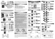
Futaba R7208SB Manual
Futaba
Radiostyret legetøj
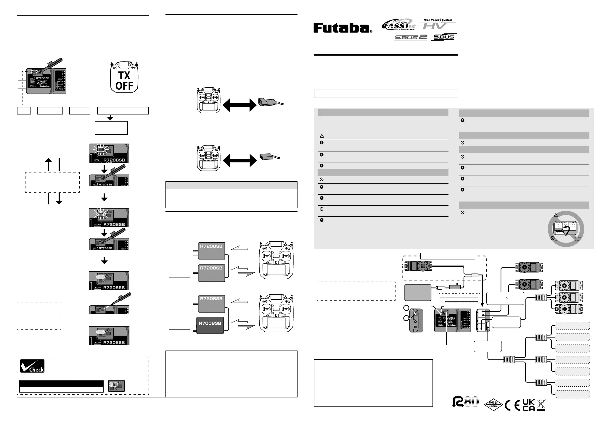
R7208SB
| Mærke: | Futaba |
| Kategori: | Radiostyret legetøj |
| Model: | R7208SB |
Har du brug for hjælp?
Hvis du har brug for hjælp til Futaba R7208SB stil et spørgsmål nedenfor, og andre brugere vil svare dig
Radiostyret legetøj Futaba Manualer
16 Juli 2025
16 Juli 2025
8 Juli 2025
8 Juli 2025
8 Juli 2025
5 Februar 2025
5 Februar 2025
5 Februar 2025

15 Januar 2025

3 Oktober 2024
Radiostyret legetøj Manualer
- Carson
- DF-Models
- Absima
- Overmax
- Silvergear
- Revell
- Proline
- SkyRC
- XciteRC
- Sharper Image
- Spektrum
- Force Engine
- Hobbywing
- Jamara
- Traxxas
Nyeste Radiostyret legetøj Manualer

1 December 2025

1 December 2025

1 December 2025

1 December 2025

1 December 2025

24 November 2025

23 November 2025
14 November 2025
10 November 2025

29 Oktober 2025