Ideal 61-357 Manual

Ideal Multimeter 61-357

Læs gratis den danske manual til Ideal 61-357 (90 sider) i kategorien Multimeter. Denne vejledning er vurderet som hjælpsom af 23 personer og har en gennemsnitlig bedømmelse på 4.9 stjerner ud af 12 anmeldelser. Har du et spørgsmål om Ideal 61-357, eller vil du spørge andre brugere om produktet?

Side 1/90
Instrucciones en español adentro / Instructions en français à l’intérieur
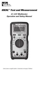
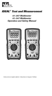
61-357 Multimeter
61-347 Multimeter
Operation and Safety Manual
IDEAL® Test and Measurement
Introduction 3 ......................................................................
Contacting IDEAL INDUSTRIES, INC 3 .........................................
Safety Information 4 ..............................................................
Warnings 4-5 ..................................................................................................
Cautions 5 .......................................................................................................
Symbols 6-7 ...................................................................................................
Operation.....................................................................8-25
Identification and description of operating controls and
functions .................................................................................................8-9
Operating Features 10-11 ...............................................................................
Using Test Leads 12 ........................................................................................
Meter Operation 13-19 ..................................................................................
Non-Contact Voltage Testing..........................................................13
Lead Warning 14 .................................................................................
Fuse Warning 14 .................................................................................
SEL Button 14 .....................................................................................
Measuring Voltage 15 .........................................................................
Measuring Continuity 16 ....................................................................
Measuring Resistance 16 ....................................................................
Measuring Capacitance 17 ..................................................................
Measuring Diodes 17 ..........................................................................
Measuring Frequency 18 ....................................................................
Measuring Temperature 18 .................................................................
Measuring Micro Amps 19 .................................................................
Measuring Milli Amps 19 ...................................................................
Measuring Amps 19 ............................................................................
Functions Operation Table 20-21 ....................................................................
Functions Indication Table 22-23 ...................................................................
Electrical Specifications 24-25 .......................................................................
Environmental Specifications 26 ...............................................
Mechanical Specifications 26 ..................................................
EMC / EMI 26 ......................................................................
FCC 27 ...........................................................................
Safety 27 ...........................................................................
Maintenance and Service 27-28 ...............................................
Table of Contents
2
Introduction
The IDEAL® 61-357 and 61-347 Digital Multimeters are auto ranging true root
mean square (TRMS) meters that measure AC and DC current (amps) in series via
test leads in the designated terminals, measures voltage, frequency, resistance,
continuity, capacitance, diodes via test-leads in the designated terminal and
measures temperature via a K-Type thermocouple. They also detect the presence
of voltage between 40V to 600V AC via a non-contact sensor in the top center of
the meter.
Contacting IDEAL INDUSTRIES, INC.
To contact IDEAL INDUSTRIES, INC., call one of the following telephone numbers:
IDEAL Industries USA Customer Service
• Phone Number: 800-435-0705
• Email: contactus@idealindustries.com
IDEAL Industries Canada Customer Service
• Phone Number: 905-683-3400
• Email: ideal_Canada@idealindustries.com
IDEAL Industries EMEA
• Phone Number: +44 (0)1925 444 446
• Email: eur.sales@idealindustries.com
IDEAL Industries Australia
• Phone Number: +61 3 9562 0175
• Email: InfoAUS@idealindustries.com
Or visit the IDEAL Electrical Website at www.idealind.com
To register your product, find manuals, watch videos, simply scan this QR code.
3
Arc Flash and Shock Hazard, Proper PPE Required. Follow all safety procedures,
wear proper PPE in accordance to NFPA 70E. Read and fully understand the
instruction manual prior to using this product. Failure to comply can result in
serious injury or death.
Identifies conditions and actions that could result in Warning -
possible death or serious injury if the hazard is realized.
Identifies conditions and actions that could result in meter dam-Caution -
age, equipment under test damage or data loss if the hazard is realized.
WARNING
Safety Information
Arc Flash and Shock Hazard, Proper PPE Required. Follow all safety procedures,
wear proper PPE in accordance to NFPA 70E and follow the guidelines below and the
instructions in this manual when operating the meter. Failure to comply can result in
serious injury or death.
Choking Hazard, Small Parts. Keep Away from Children. Sharp Objects
Hazard, This is not a toy. It is not for use or play by children. Keep Away from
Children. Failure to do so can result in serious injury.
• Only experienced or technically competent consumers should use this
equipment. When in doubt, call an experienced electrician to make any and all
necessary repairs or installations. At all times, perform any necessary work on
a de-energized circuit that has had its circuit breaker turned off and has been
locked out.
• Use the Meter only as specified in this manual or protection provided by the
Meter can be compromised.
• Before using or connecting the Meter, visually inspect it to ensure the cases
are not cracked and the back case is securely in place. Do not use if the Meter
appears damaged.
• Before using the test leads, inspect carefully for damaged insulation, exposed
metal or cracked probes. Check test leads for continuity. Do not use leads if they
appear damaged.
• Use only approved test leads. Do not use improvised connections that could
present a safety hazard.
• When using the probes, keep fingers behind the guard ring on the probes.
• Connect the common test lead before connecting the live test lead. When
disconnecting test leads, disconnect the live test lead first.
• This Meter is intended for use by qualified electricians. Follow NFPA 70E
Standards for Electrical Safety in the Workplace when using this Meter.
• Do not use without the batteries correctly in place and the battery door closed
and secured.
• Do not use Meter if it operates incorrectly as protection may be compromised.
When in doubt, have the Meter serviced.
• When servicing the Meter, use only specified replacement parts.
4
5
Arc Flash and Shock Hazard, Proper PPE Required. Follow all safety
procedures, wear proper PPE in accordance to NFPA 70E and follow
the guidelines below and the instructions in this manual when
operating the meter. Failure to comply can result in serious injury
or death.
• Have the Meter serviced only by qualified service personnel.
• Do not use the Meter around explosive gas, dust, or vapor, or during
electrical storms, or in wet environments.
• When measuring, keep fingers behind the Tactile Barrier. See “The Meter”
on pg. 8 and 9.
• Do not apply more than the rated voltage, as marked on the Meter, between
the terminals or between any terminal and earth ground.
• To avoid false readings that can lead to electrical shock and injury, replace
the batteries as soon as the low battery indicator ( ) appears.
• Remove the test leads from the circuit prior to removing the battery door.
• Voltages exceeding 30VAC or 60VDC pose a shock hazard so use caution.
• Always ensure that test leads are secured so that they cannot be accidentally
snagged or tripped over.
• Do not work alone so that assistance can be rendered in an emergency.
• Use extreme caution when working around bare conductors or bus bars.
Contact with the conductor could result in electric shock.
• Adhere to local and national safety codes. Individual protective equipment
must be used to prevent shock and arc blast injury where hazardous live
conductors are exposed.
• Disconnect circuit power and discharge all high-voltage capacitors before
you measure resistance, continuity, or capacitance.
• Never operate the Meter with the back cover removed or the case open.
• These meters are IP52 dust and water resistant. Following any contact with
water, thoroughly dry meter and test lead jacks prior to subsequent use.
Cancer and Reproductive Harm - www.P65Warnings.ca.gov
Meter damage, equipment under test damage or data loss can occur
if the following guidelines are not adhered to.
• Use the proper terminals, function, and range for the measurement
application.
• Clean the case and accessories with a damp cloth and mild detergents only.
Do not use abrasives or solvents. Make sure the meter is completely dry
before use.
CAUTION
WARNING
Symbols & Descriptions
SYMBOL DESCRIPTION
Arc Flash and Shock Hazard
Shock Hazard
Warning or Caution
Choking Hazard
AC (Alternating Current)
DC (Direct Current)
Low Battery Indicator
Earth Ground
10 A Maximum Current Specification
CAT III IEC Measurement Category III
CAT III has protection against transients in equipment in fixed-
equipment installations such as distribution panels feeders,
and short branch circuits. Also included are lighting systems in
larger buildings.
CAT IV IEC Measurement Category IV
CAT IV has protection against transients from the primary
supply level such as a Meter or overhead or underground utility
service.
NCV Non-Contact Voltage Sensing
NCV Non-Contact Voltage Sensing Point
AAmperage AC and DC
Hz Frequency measured via the test leads
VVoltage AC or DC
Hz% Frequency displayed as % measured with AC Voltage
6
SYMBOL DESCRIPTION
ΩOhms
Continuity
Capacitance
Diode
°F °C Temperature Degrees Fahrenheit / Celsius
LCD Liquid Crystal Display
MAX/MIN Display MAX and MIN Measurement Variations
Range Auto or Manual Range Selection
Delta (Relative)
Double Insulation
Do not dispose of this product as unsorted municipal waste.
It must be properly disposed of in accordance with local
regulations. Please see www.epa.gov or www.erecycle.org for
additional information.
Conforms to applicable North American Safety Standards
Conforms to applicable Australian Safety Standards
Conforms to European Directives
NOTE: The Measurement Category (CAT) and voltage rating of any combination
of test probe, test probe accessory, current clamp accessory, and the Meter is the
LOWEST rating of any individual component.
7
Identification and Description of Operating
Controls and Functions for the 61-347 and 61-357
Digital Multimeters:
1. HV, & Continuity LED
2. LCD Display
3. Tactile Barrier
4. Backlight Button
5. Rubber Boot
6. Volts/Ohms Input Terminal
7. Common (COM) Input Terminal
8. Mili Amps, Micro Amps Input Terminal
9. Amps Input Terminal
10. Measuring Functions Dial
11. Function Select Button
12. Function Buttons
13. NCV Sensing Point
14. Analog Bar Graph (61-357 only)
8
Operation
4
1
3
6
11
10
2
5
12
14
9
7
8
9
13
High Voltage Warning (HI-V)
The meter beeps once (for 1 second) and a red LED illuminates and remains on as
long as the voltage remains above 30V AC or DC, or when the meter’s voltage range
is exceeded.
NOTE: This feature does not work in the Ohm, capacitor, continuity or amperage
modes.
Data Hold Feature
Press the Hold button to toggle in and out of the data hold mode. “H” appears in the
upper left of the meter display when data hold is active. Use the data hold feature to
lock a measurement reading on the display. Press the Hold button again to unlock
the display and obtain a real-time reading.
MAX/MIN Feature
The MAX/MIN records the maximum and minimum measured value. Press the
MAX/MIN button to activate this feature and to toggle between MAX, and MIN
readings. The unit will continually capture MAX and MIN values over time.
Depressing the MAX/MIN button for >2 sec. exits the MAX/MIN mode.
NOTE: When the MAX/MIN function is activated, the Auto Power Off (APO) feature
will be disabled. When you exit the MAX/MIN function, Auto Power Off feature is
enabled.
REL Feature
A short press of the ‘ ’ button will activate or deactivate the REL function.
Range
The meter is auto ranging, however the user may select a specific range by pressing
the range button repeatedly.
Auto Power Off (APO) Feature Disable
The meter automatically powers itself down after about 30 minutes of no use. Press
any button, and the meter will wake up and display the last reading taken before
power down. To Disable APO, press and hold the SEL button while turning the dial
to any desired function. When APO is defeated, the “APO” will be removed from the
display. Turning the meter off and back on will restore the APO default.
Analog Bar Graph
An analog scale representation of the digital readout values. (61-357 only)
10
Operating Features
11
Press the Backlight button on the meter to turn the backlight on and off. The white
backlight will remain lit for about 5 minutes before it automatically turns off to
conserve battery power. Or turn the backlight off by pressing the button again.
Backlight
Backlight is selectable
to be on in all
functions.
WARNING: Arc Flash and Shock Hazard, Proper PPE Required.
Follow all safety procedures, wear proper PPE in accordance to NFPA 70E and
assure that the Protective Caps are in place when operating a properly rated
electrical meter/tester using the TL-757 Test Leads in a CAT IV 600V or CAT III
1000V environment.
This meter is intended for use with the IDEAL TL-757 lead set (provided with this
product) or equivalent. The lead set must comply with requirements for Overvoltage
and Measurement Categories CAT IV 600V CAT III 1000V.
12
Using Test Leads
WARNING: Arc Flash and Shock Hazard, Proper PPE Required.
Follow all safety procedures, wear proper PPE in accordance to NFPA 70E and
follow the guidelines below and the instructions in this manual when operating
the meter with TL-757 Test Leads or equivalent. Test Leads must be rated for the
electrical environment the meter is being used in and have a voltage rating of at
least the voltage of the circuit to be measured. Failure to comply can result in
serious injury or death.
Choking Hazard, Small Parts. Keep Away from .....
Children. Sharp Objects Hazard, This is not a toy. It is not for use or play by
children. Failure to do so can result in serious injury or death.
• Use only approved test leads. Do not use improvised connections that could
present a safety hazard.
• Ensure that the test leads are inserted into the correct input jacks when
measuring AC or DC current.
• Prior to using the test leads, inspect them carefully for damaged insulation,
exposed metal or bent probes. Check test leads for continuity. Do not use
leads if they appear damaged.
• When using the probes, keep fingers behind the guard rings on the probes.
• Connect the common test lead before connecting the live test lead. When
disconnecting test leads, disconnect the live test lead first.
• Always ensure that test leads are secured so that they cannot be accidentally
snagged or tripped over.
• These meters are IP52 dust and water resistant. Following any contact with
water, thoroughly dry meter and test lead jacks prior to subsequent use.
Protective Cap Guard Ring
CAT III 1000V, CAT IV 600V (with cap on)
Meter Operation
13
Non-Contact Voltage Sensing
First, rotate the function key to the position. Place the sensing point marked NCV
with NCV close to an AC outlet (or any AC conductor such as light switches or
power cords) and scan back and forth across the outlet. The meter beeps On/Off
continuously and the Red NCV LED above the display flashes if the sensing antenna
detects live voltage greater than 40V AC (50 -60 Hz). Voltages with frequencies
higher than 60Hz or electrostatic charges may also be detected by the NCV sensing
antenna. To differentiate between hot and neutral in an outlet, place the NCV tab
directly next to each slot in the outlet. The tone (buzzer) will sound over the slot
that is energized and not on the neutral slot. Either test lead can also be used to
differentiate between the hot and neutral. Plug the red or black test lead into the
V input jack on the meter. With the function switch in the NCV position, insert the
probe end of just one probe into the slots on the outlet. The meter will beep and the
Red LED will flash when a hot conductor is contacted.
NOTE: While the NCV is a helpful function, it is ALWAYS
RECOMMENDED that the operator verify that any electrical conductor is
completely de-energized and that no voltage is present by measuring
for voltage AND CONFIRMING THAT NO VOLTAGE IS PRESENT and that
all applicable PPE and lock out tag out procedures be followed before
attempting any work on ANY electrical distribution system.
14
SEL Button
Lead Warning Fuse Warning
Lead Warning: When inserting the test
lead into any amperage input terminal, but
the rotary function switch set to the IS NOT
correct relative amperage position, the meter
will beep at 3Hz, LCD will display ” LEAd
and “ ”, flashes at 3Hz. If any amperage .
function is selected first, but the test lead IS
NOT in the relative amperage input jack,the
meter will also beep at 3Hz and the LCD will
display “ ” and “ ”, flashes at 3Hz.LEAd
Fuse Notification: The test leads
CANNOT be short circuited or used for
measuring while testing the fuse.
1. If the 600mA/1000V fuse is blown,
setting the rotary switch to the “mA”
or “uA” setting, the LCD will display
” and “ ”, and the buzzer FUSE .
will beep continuously at the same time.
2. If the 11A/1000V fuse is blown,
setting the rotary switch to the “A”
setting, the LCD will display “ FUSE
and “ ”, and the buzzer will beep .
continuously at the same time.
e SEL Button allows the user to toggle between multiple
nctions when the function dial is used to select a specific
nction. This can include but is not limited to toggling between
grees F and C, AC and DC voltage or current, continuity,
sistance, capacitance and diode measurements.
Measuring AC ( ) or DC ( ) Voltage
15
*Note: When measuring AC voltage, Ghost or stray voltages (caused by
induced voltages coupling from one parallel conductor to the next as found when
measuring one conductor in multiple conductor circuits) may cause an incorrect
value. Selecting the Low impedance position (LoZ) on the dial, (see inset above)
while measuring voltage with the 61-357 will defeat the influence of Ghost or Stray
voltage.
Use caution when using the LoZ function on equipment that may Caution -
be damaged by being connected to a low impedance source.
To assist with voltage readings, a bar graph will appear in the display.
16
Verifying Continuity ( )
• Verify the circuit is de-energized.
• The meter will sense the level of resistance and beep if the resistance is less
than 10 s to confirm that continuity is present.Ω
• The red LED will illuminate and the resistance value will be displayed.
• The default setting is Continuity
Verify the circuit is de-energized to obtain accurate measurements.
To exit Continuity and enter the Resistance mode, press the SEL button.
Measuring Resistance (Ohms / )Ω
17
• To exit Resistance and enter the Capacitance mode, press the SEL button.
• To exit Capacitance and enter the Diode Test mode, press the SEL button.
Measuring Capacitance ( )
Measuring Diodes ( )
Measuring Frequency ( Hz )
Measuring Temperature ( °F °C )
Hz using Voltage
For % Duty Cycle Press the
SEL button
Press SEL to toggle
between F and C
18
Measuring Micro Amps (μA)
Measuring Milli Amps (mA)
Measuring Amps (A)
19
CAUTION
Meter damage. Measure current in
Micro Amps for a maximum duration
of 10 minutes. Failure to comply can
result in meter damage.
CAUTION
Meter damage. Measure current in
Milliamps for a maximum duration
of 1 minute. Failure to comply can
result in meter damage.
CAUTION
Meter damage. Measure current in
Amps for a maximum duration of 10
seconds. Failure to comply can result
in meter damage.
Button Response Default Function
HOLD HOLD: All Functions Normal Measurement
SEL /
ACA / DCA DCA
ACV/DCV ACV
Hz/% Hz
/ Ω / / Continuity
°F/°C °F
RANGE ACV, DCV, ACA, DCA, ΩAuto range (LCD display
“AUTO”)
MAX/MIN ACV, DCV, ACA, DCA,
Ω, °F/°C Normal Measurement
: ACV, DCV, ACA, DCA,
CAP, , °F/°CΩNormal Measurement
Non-Contact Voltage Indication
Functions Operation Table
20
Operation
Short Press: Circularly enter or exit the data hold mode, LCD will display “ “ after enter
HOLD function.
1) Short press: Circularly select the relative measurement function.
2) When in HOLD, RANGE, MAX/MIN, REL function, Short press the SEL key to quit current
function and circularly change relative Select function.
1) Short press the RANGE key to enter manual range mode (LCD will not display “AUTO”), and
the current range, press again to enter cyclical selection range. Long press: exits manual range
and enters Auto range. Switching measurement setting or restarting the unit returns the unit to
the default setting.
2) In HOLD, MAX/MIN, REL function, Short press the RANGE key to exit the current function and
enter the relative range function.
1) Short press: enter “MAX/MIN” statistics mode, continuously updates the data, and you can
circularly view the maximum value minimum value maximum value. Long press: exits
statistical mode and returns to the normal working mode. After pressing the REL key, and then
short pressing MAX/MIN, the unit will show the MAX/MIN after deducting the initial offset value.
2) When HOLD function is in use, MAX/MIN is invalid.
3) After entering the statistical mode, exit the automatic range at the same time and enter into
the current range, the APO will be disabled; exit the MAX/MIN function to restore the automatic
range and automatic shutdown.
4) In the statistical mode, a short press of the HOLD key will stop refreshing the statistical data.
At the same time, a short press of the MAX/MIN key can review the stored data of MAX/MIN, a
short press of the HOLD key exits HOLD to continue refreshing the statistical data.
1) Short press: Circularly enter or exit REL function (when entering REL function, LCD will
display “ ” symbol )
2) Entering the REL function, exits auto range and enters into the current range.
3) Entering the REL measurement mode does not change the actual measurable range of the
current range
4) When HOLD or MAX/MIN is in use, REL function is invalid.
Displays “EF” – Electromagnetic Field
21
Functions Indication Table
Function Description
Auto Range Auto detects and displays most pertinent range for measured value.
LCD One LCD. Displays a “-” symbol for all negative readings, displays “AC”
for alternating current or “DC” for direct current and displays “Amps” for
current measurement.
LCD Backlight White backlight. The backlight will automatically power off after 5 minutes
of inactivated
High Voltage
Alarm
1) Only applicable to ACV / DCV
2) For ACV and DCV, when voltages in excess of 30V is measured or the
measured voltage is over limit, then the high voltage alarm symbol
” appears on the screen display, simultaneously the LED remains .
RED and beeping lasts for 1 second then becomes silent during
measurement.
Regular Prompt 1) When turning the dial switch to any setting position except OFF, the
buzzer will beep one time and the NCV LED flashes one time.
2) When the button selection is valid, the buzzer will beep one time; When
the button is invalid, the buzzer will beep twice.
3) About 1 minute before the automatic shutdown, the buzzer will beep 5
times continuously, and 1 long beep before the unit shuts down.
4) When the automatic shutdown function is canceled, the buzzer will
beep 5 times when it reaches the APO time setting.
Over Range
Indication
LCD displays “OL” when over range is encountered.
Lead Warning When inserting the test lead into any amperage input terminal, but the
rotary function switch set to the relative amperage position, the IS NOT
meter will beep at 3Hz, LCD will display ” and “ ”, flashes at LEAd .
3Hz. If any amperage function is selected first, but the test lead in IS NOT
relative amperage input jack,the meter will also beep at 3Hz and the LCD
will display “ ” and “ ”, flashes at 3Hz.LEAd .
22
Function Description
Fuse Notification The test leads be short circuited or used for measuring while CANNOT
testing the fuse.
1. If the 600mA/1000V fuse is blown, setting the rotary switch to the
“mA” or “uA” setting, the LCD will display “ ” and , and FUSE
the buzzer will beep continuously at the same time.
2. If the 11A/1000V fuse is blown, setting the rotary switch to the “A”
setting, the LCD will display “ ” and “ ”, and the buzzer will FUSE .
beep continuously at the same time.
Low Battery
Indication
When the battery voltage < 3.6 ±0.2V, the low battery indication ‘
is displayed on the screen and the meter will still work normally. When
the battery voltage drops to less than 3.1 ±0.2V, “bAtt” is displayed for
5 seconds then shuts off. When the battery voltage is less than 3.2V,
accuracy is no longer assured.
APO The unit will be automatically power off after 30 minutes of inactivity
and enter the low-power state. Current draw is approx. 50 micro A.
Restore APO All the buttons can wake up the unit, or rotate the dial switch to the OFF
setting and then turn the unit back on to wake it up.
Disable Auto
Power Off
Function
Pressing the “Select” key while turning on the unit on at the same time,
will cancel the auto shutdown function. Buzzer will beep 5 times and the
LCD will not display the “APO” symbol.
Mechanical
Housing
Single Injection Molding with rubber boot.
23
Electrical Specifications
Function Range
61-347 & 61-357
Resolution Accuracy
±(a%+b)
AC Voltage (V)
TRMS
(61-357 has LoZ)
600mV 0.1mV ±(1.5%+8)
6V 0.001V
±(1.3%+5)60.00V 0.01V
600.0V 0.1V
1000V 1V ±(1.5%+5)
AC Current (A)
TRMS
600.0μA 0.1μA
±(2%+5)
6000μA 1μA
60.00mA 0.01mA
600.0mA 0.1mA
6.000A 0.001A
±(2.5%+5)
10.00A 0.01A
DC Voltage (V)
600mV 0.1mV ±(1.5%+8)
6V 0.001V
±(1.3%+5)60.00V 0.01V
600.0V 0.1V
1000V 1V ±(1.5%+5)
DC Current (A)
600.0μA 0.1μA
±(2%+5)
6000μA 1μA
60.00mA 0.01mA
600.0mA 0.1mA
6.000A 0.001A
±(2.5%+5)
10.00A 0.01A
Resistance ( )Ω
600.0 0.1Ω Ω
±(1.5%+5)6.000k 0.001kΩ Ω
60.00k 0.01kΩ Ω
600.0k 0.1kΩ Ω
±(2%+5)6.000M 0.001MΩ Ω
60.00M 0.01MΩ Ω
24
25
Function Range
61-347 & 61-357
Resolution Accuracy
±(a%+b)
Capacitance
600.0nF 0.1nF
±(5%+15)
6.000uF 0.001uF
60.00uF 0.01uF
600.0uF 0.1uF
6000uF 1uF ±10%
Frequency Hz 9.999Hz ~ 9.999KHz 0.001Hz ~
0.1KHz ±(0.5%+5)
Duty Cycle % 0.1%~99.9% 0.1%
Temp. °F -40~1832°F 1°F ±(2.0%+7)@-40~32°F
±(2.0%+6)@33~1832°F
Temp. °C -40~1000°C 1°C ±(2.0%+4)@-40~0°C
±(2.0%+3)@1~1000°C
Continuity 0.1 Ω
≤ Ω10 : Buzzer beeps
and red indicator LED
illuminates continuously
≥ Ω70 : No buzzer beep
Diode test 0.001V
Silicon PN joint with
forward voltage about
0.5V to 0.8V
NCV 40-600V
40V/(50~60Hz), with direct wire contact,
red indicator LED flashes at a frequency of
3Hz , and the buzzer beeps at a frequency
of 3Hz simultanously
1. Overload Protection: 1000VRMS MAX Fuses FF 0.6A 1000V and FF 11A 1000V
2. Accuracy a is % of reading and b is LSD (Least Significant Digit).
Environmental Specifications
Operating Temperature: 32ºF to 86ºF (0ºC to 30ºC) (80%RH)
86ºF to 140ºF (30ºC to 40ºC) (75%RH)
104ºF to 122ºF (40ºC to 50ºC) (45%RH)
Operating Altitude: < 6500 ft (< 2000 m)
Storage Temperature: 14ºF to 140ºF (-10ºC to 60ºC) (<80%RH)
Mechanical Specifications
Dimensions (L x W x H): 7.83 in. x 3.74 in. x 2.24 in.
(199 mm. x 95 mm. x 57 mm.)
Weight: 1.147 LBS (0.52 KG)
Display: LCD
Display Count: 6000
Power Source: 3 x 1.5V AAA
Battery Life: 100 Hours Typical
Ingress Protection Rating: IP52 dust and water resistant
EMC/EMI
26
CISPR 22 3rd Edition. Class B Limits.
EN 55032
CISPR 32
CISPR 11
FCC 15. 107 with reference to Section 15.109 (g).
ICES-003
EN 61326-2-2 Sec 6.4.2.101
Intended for indoor use
USA (FCC)
47 CFR 15 subpart B. This product is considered an exempt device per clause
15.103.
Safety
Complies with the following:
UL 61010-1, 3rd Edition, May 11, 2012, Revised November 21 2018, CAN/
CSA-C22.2 No. 61010-1-12, 3rd Edition, Amendment 1:2018, Revision dated
November 21 2018,
IEC 61010-2-033: 2019
Overvoltage CAT IV 600V CAT III 1000V.
Any voltages exceeding the defined maximum voltage measurement categories
described above are outside the normal use of the equipment and protection cannot
be guaranteed.
Pollution Degree Class 2
27
Equipment Maintenance and Service
Meter Inspection
Do not use if meter appears damaged. Visually inspect the meter to ensure the case
is not cracked.
Test Lead Inspection
Inspect and replace test leads if insulation is damaged, metal is exposed, or probes
are cracked. Pay particular attention to the insulation surrounding the connectors.
Thermocouple Inspection
Inspect the thermocouple for signs of wear or breakage. Replace if necessary to
guarantee accuracy of readings.
Maintenance and Service
28
Battery Inspection/Replacement
Inspect the battery compartment monthly for any signs of degradation. Low battery
voltages will cause inaccuracies in readings. Remove the batteries for storage
or if the meter will not be used for longer than one month. Battery leakage will
compromise the safety of the meter and cause irreparable damage to internal
components.
Maintenance and Storage
Switch off and disconnect the meter completely before carrying out any
maintenance. Clean the case with a damp cloth and mild detergent. Do not use
abrasives or solvents. Keep away from liquids and ensure the meter is completely
dry before use.
Service and Replacement Parts
For the 10 Amp Terminal – 11 Amp 1000V AC DC IR30kA Fast Acting Fuse,
10 x 38 mm Ceramic or equivalent
For the 600 Milli Amp Terminal – 600 Milli Amp 1000V AC DC Fast Acting
Fuse, 6 x 32 mm Ceramic or equivalent
To ensure the meter is in a safe state of operation, make sure the fuses are
properly seated and that the battery cover is secured to the back of the meter.
With the leads in the terminals but not connected to or touching any voltage
source, turn the function dial to the applicable Amperage setting and verify the
FUSE indicator is NOT displayed. This indicates that the replacement fuse in not
blown or popped. Use only specified replacement fuses.
Shock Hazard. Remove the test leads from the circuit prior to removing the battery
cover. Failure to comply can result in serious injury or death.
29
In order to preserve, protect and improve the quality of the environment, protect
human health and utilize natural resources prudently and rationally, the user should
return unserviceable product to relevant facilities in accordance with statutory
regulations. The crossed-out wheeled bin indicates the product needs to be
disposed separately and not as municipal waste.
Do not dispose of this product as unsorted municipal waste. It must be properly
disposed of in accordance with local regulations. Please see www.epa.gov or www.
erecycle.org for additional information.
The user is legally obliged to return used batteries and accumulators. Disposing
used batteries in household waste is prohibited! Batteries/accumulators containing
hazardous substances are marked with the crossed-out wheeled bin. The symbol
indicates that the product is forbidden to be disposed via domestic refuse. The
chemical symbols for the respective hazardous substances are = Cadmium, Cd Hg
= Mercury, = Lead.Pb
You can return used batteries/accumulators free of charge to any collecting point
of your local authority, our stores, or where batteries/accumulators are sold.
Consequently, you must comply with your legal obligations and contribute to
environmental protection.
Disposal of Waste, Electrical & Electronic Equipment
Disposal of Used Batteries/Accumulators
TWO YEAR LIMITED WARRANTY
This tester is warranted to the original purchaser against defects in material and
workmanship for a period of two (2) years from date of purchase. With proof of
purchase from an authorized IDEAL distributor, a defective tester will be repaired or
replaced with the same product or a functionally equivalent product, at the option
of IDEAL INDUSTRIES, INC. during the warranty period, subject to verification
of the defect or malfunction. Warranty does not cover consumables such as
fuses, batteries, and excludes defects caused by leakage from batteries, abuse,
mishandling, dropping, ordinary wear and tear, misuse, neglect, unauthorized
repair, improper use, alterations, accidents or any causes beyond IDEALs
reasonable control. Consequential or incidental damages are not recoverable under
this warranty. Some states do not allow the exclusion or limitation of incidental or
consequential damages, so the above limitation or exclusion may not apply to you.
This LIMITED WARRANTY gives you specific legal rights, which vary from state to
state. This warranty constitutes the sole and exclusive remedy of the purchaser and
the exclusive liability of IDEAL, and is in lieu of any and all other warranties, and
expressly disclaims all other warranties, implied, or statutory as to merchantability,
fitness for purpose sold, description, quality productiveness, or any other matter.
No agent, distributor or other supplier has the authority to modify or amend this
warranty or make other representations or warranties other than those contained
in this warranty without express written authorization from IDEAL. For warranty
service, call IDEAL customer service at 1-800-435-0705.
Made in China
IDEAL INDUSTRIES, INC. Sycamore, IL 60178, U.S.A. 800-435-0705 www.Idealind.com ND 9016-2
Scan the barcode on the right to see the new IDEAL T&M Product Line
Instrucciones en español adentro / Instructions en français à l’intérieur
Medidor 61-357
Medidor 61-347 Multimeter
Manual de Operación y Seguridad
IDEAL® Prueba y Medición
Introducción 33 ...................................................................
Cómo contactar a IDEAL INDUSTRIES, INC. 33 ..............................
Información de Seguridad 34 ...................................................
Advertencias .........................................................................................34-35
Precauciones ..............................................................................................35
Símbolos ..............................................................................................36-37
Operación 38-55 ..................................................................
Identificación y descripción de controles de operación y funciones 38-39 ....
Funciones de Operación 40-41 .......................................................................
Uso de los Cables de Prueba 42 ....................................................................
Operación del Medidor 43-47 .........................................................................
Prueba de Voltaje Sin Contacto 43 ......................................................
Advertencia de Cable 44 .....................................................................
Advertencia de Fusible 44 ...................................................................
Botón SEL 44 ......................................................................................
Medición de Voltaje 45 .......................................................................
Medición de Continuidad 46 ...............................................................
Medición de Resistencia 46 ................................................................
Medición de Capacitancia 47 ..............................................................
Medición de Diodos 47 .......................................................................
Medición de Frecuencia 48 .................................................................
Medición de Temperatura 48 ...............................................................
Medición de Micro Amperios (A) 49 ..................................................
Medición de Mili Amperios (mA) 49 ...................................................
Medición de Amperios (A) 49 .............................................................
Tabla de Operaciones de Funciones 50-51 .....................................................
Tabla de Indicación de Funciones 52-53 ........................................................
Especificaciones Eléctricas 54-55 ...................................................................
Especificaciones Ambientales 56 ..............................................
Especificaciones Mecánicas 56 ................................................
EMC/EMI........................................................................ 56
FCC 57 ..............................................................................
Seguridad 57 ......................................................................
Mantenimiento y Servicio 57-58 ...............................................
Índice
32
Introducción
Los Medidores Digitales IDEAL® 61-357 y 61-347 son medidores con rango
automático de valor cuadrático medio verdadero (TRMS) que miden corriente CA y
CD (amperios) en serie a través de cables de prueba en las terminales designadas,
miden voltaje, frecuencia y resistencia, continuidad, capacitancia, diodos a través
de cables de prueba en las terminales designadas y miden la temperatura a través
de un termopar Tipo K. También detectan la presencia de voltaje entre 40V y 600V
CA a través de un sensor sin contacto en la parte superior central del medidor.
Cómo contactar a IDEAL INDUSTRIES, INC.
Para contactar a IDEAL INDUSTRIES, INC., Llame a uno de los siguientes números
de teléfono:
Servicio al cliente de IDEAL Industries USA
• Número de Teléfono: 800-435-0705
• Correo electrónico: contactus@idealindustries.com
Servicio al cliente de IDEAL Industries Canadá
• Número de Teléfono: 905-683-3400
• Correo electrónico: ideal_Canada@idealindustries.com
IDEAL Industries EMEA
• Número de Teléfono: +44 (0)1925 444 446
• Correo electrónico: eur.sales@idealindustries.com
IDEAL Industries Australia
• Número de Teléfono: +61 3 9562 0175
• Correo electrónico: InfoAUS@idealindustries.com
O visite el sitio web de IDEAL Electrical en www.idealind.com para registrar su
producto, encontrar manuales, ver videos, simplemente escanee este código QR.
33
Peligro de Arco Eléctrico y Descarga Eléctrica, se Requiere el EPP Adecuado. Siga
todos los procedimientos de seguridad, use el EPP adecuado de acuerdo con NFPA
70E. Lea y comprenda completamente el manual de instrucciones antes de usar
este producto. El incumplimiento puede resultar en lesiones graves o la muerte.
Identifica condiciones y acciones que podrían Advertencia -
provocar la muerte o lesiones graves si se toma el riesgo.
- Identifica condiciones y acciones que podrían resultar en Precaución
daño al medidor, daño al equipo bajo prueba o pérdida de datos si se toma el
ADVERTENCIA
Información de Seguridad
Peligro de Arco Eléctrico y Descarga Eléctrica, se Requiere el EPP Adecuado. Siga
todos los procedimientos de seguridad, use el EPP adecuado de acuerdo con NFPA
70E y siga las pautas a continuación y las instrucciones de este manual cuando
opere el medidor. El incumplimiento puede resultar en lesiones graves o la muerte.
Peligro de Asfixia, Partes Pequeñas. Mantener Fuera del Alcance de los
Niños. Peligro de Objetos Afilados, Esto no es un juguete. No es para uso o
juego de niños. Mantener Fuera del Alcance de los Niños. No hacerlo puede
resultar en lesiones graves.
• Solo los consumidores experimentados o técnicamente competentes deben
utilizar este equipo. En caso de duda, llame a un electricista experimentado
para que realice todas las reparaciones o instalaciones necesarias. En todo
momento, realice cualquier trabajo necesario en un circuito desenergizado
al que se le haya apagado el cortacircuitos y se haya bloqueado.
• Utilice el Medidor solo como se especifica en este manual o la protección
proporcionada por el Medidor puede verse comprometida.
• Antes de usar o conectar el Medidor, revíselo visualmente para asegurarse
de que las carcasas no estén agrietadas y que la carcasa posterior esté bien
colocada. No use el Medidor sí parece dañado.
• Antes de usar los cables de prueba, revíselos cuidadosamente para detectar
daños en el aislamiento, metal expuesto o sondas rajadas. Compruebe las
puntas de prueba para verificar si hay continuidad.
• No utilice los cables sí parecen dañados.
• Utilice solo cables de prueba aprobados. No utilice conexiones
improvisadas que puedan representar un peligro para la seguridad.
• Nunca mida corriente CA mientras los cables de prueba estén insertados en
las tomas de entrada.
• Cuando utilice las sondas, mantenga los dedos detrás de los protectores de
dedos en las sondas.
• Conecte el cable de prueba común antes de conectar el cable de prueba con
corriente. Al desconectar los cables de prueba, desconecte primero el cable
de prueba con corriente.
• Este Medidor está diseñado para ser usado por electricistas calificados.
Siga las Normas NFPA 70E para Seguridad Eléctrica en el lugar de trabajo
cuando utilice este Medidor.
• No lo utilice sin las baterías correctamente colocadas y la tapa de las
baterías cerrada y asegurada.
• No utilice el Medidor si funciona incorrectamente, p34-ya que la protección
puede verse comprometida. En caso de duda, lleve el Medidor a que le
hagan servicio.
• Al realizar el servicio al Medidor, use solo los repuestos especificados. 34
35
Peligro de Arco Eléctrico y Descarga Eléctrica, se Requiere el EPP Adecuado. Siga
todos los procedimientos de seguridad, use el EPP adecuado de acuerdo con NFPA
70E y siga las pautas a continuación y las instrucciones de este manual cuando
opere el medidor. El incumplimiento puede resultar en lesiones graves o la muerte.
• Únicamente permita que el servicio del Medidor lo lleve a cabo personal de
servicio calificado.
• No utilice el Medidor cerca de gases, polvo o vapores explosivos, o durante
tormentas eléctricas o en entornos húmedos.
• Al medir, mantenga los dedos detrás de la Barrera Táctil. Consulte “El
Medidor” en la pág. 38 y 39.
• No aplique voltaje por encima del voltaje nominal, según lo indicado en el
Medidor, entre las terminales o entre cualquier terminal y conexión a tierra.
• Para evitar lecturas falsas que pueden provocar descargas eléctricas y
lesiones, reemplace las baterías tan pronto como aparezca el indicador de
baterías bajas ( ).
• Retire los cables de prueba del circuito antes de quitar la tapa de las baterías.
• Los voltajes que excedan los 30VCA o 60VCD representan un peligro de
descarga eléctrica, así que tenga cuidado.
• Asegúrese siempre de que los cables de prueba estén asegurados para que
no puedan ser enganchados accidentalment o causen tropiezos.
• No trabaje solo para que se pueda prestar asistencia en caso de emergencia.
• Tenga mucho cuidado al trabajar cerca de conductores pelados o barras
colectoras. El contacto con el conductor podría provocar una descarga
eléctrica.
• Cumpla con los códigos de seguridad locales y nacionales. Se debe utilizar
equipo de protección individual para evitar descargas eléctricas y lesiones
por explosión de arco cuando se exponen conductores activos peligrosos.
• Desconecte la alimentación del circuito y descargue todos los capacitores
de alto voltaje antes de medir la resistencia, la continuidad o la capacitancia.
• No mida corriente en circuitos que transporten más de 600V o 600A con la
Mordaza del Medidor.
• Nunca opere el Medidor con la cubierta trasera removida o la carcasa abierta.
• Estos medidores son resistentes al agua y al polvo IP52. Después de
cualquier contacto con el agua, seque completamente el medidor y los
conectores de cables de prueba antes de usarlos posteriormente.
Cáncer y Daño Reproductivo - www.P65Warnings.ca.gov
Daño al Medidor, daño al equipo bajo prueba o la pérdida de los datos puede
ocurrir si no se siguen las siguientes pautas.
• Utilice las terminales, la función, y el rango apropiado para la aplicación de
la medida.
• Únicamente limpie la carcasa y los accesorios con un paño húmedo y
detergentes suaves. No utilice abrasivos o solventes. Asegúrese de que el
medidor esté totalmente seco antes de usar.
PRECAUCIÓN
ADVERTENCIA
Símbolos & Descripciones
SÍMBOLO DESCRIPCIÓN
Peligro de Arco Eléctrico y Descarga Eléctrica
Peligro de Descarga Eléctrica
Advertencia o Precaución
Peligro de Asfixia
CA (Corriente Alterna)
CD (Corriente Directa)
Indicador de Carga de la Batería
Tierra
10 A Especificación de Corriente Máxima
CAT III Categoría de Medición IEC III
CAT III tiene protección contra transitorios en equipos en
instalaciones de equipos fijos como paneles de distribución,
alimentadores y circuitos derivados cortos. También se incluyen
sistemas de iluminación en edificios más grandes.
CAT IV Categoría de Medición IEC IV
CAT IV tiene protección contra transitorios del nivel de
suministro primario, como un Contador o un servicio público
subterráneo o aéreo.
NCV Detección de Voltaje Sin Contacto
NCV Punto de Detección de Voltaje Sin Contacto
AAmperaje CA y/o CD (depende del modelo)
Hz Frecuencia medida a través del cabezal de la pinza
VVoltaje CA o CD
Hz% Frecuencia mostrada como % medido con Voltaje de CA
36
SÍMBOLO DESCRIPCIÓN
ΩOhmios
Continuidad
Capacitancia
Diodo
°F °C Grados de Temperatura Fahrenheit/Celsius
LCD Pantalla de Cristal Líquido
MAX/MIN Mostrar Variaciones de Medición MAX y MIN
Range Selección de Rango Automático o Manual
Delta (Relativo)
Aislamiento Doble
No elimine este producto como residuo municipal sin clasificar.
Debe desecharse adecuadamente de acuerdo con las regula-
ciones locales. Por favor visite www.epa.gov o www.erecycle.org
para obtener información adicional.
Cumple con los Estándares de Seguridad Norteamericanos
aplicables
Cumple con los Estándares de Seguridad Australianos
aplicables
Cumple con las Directivas Europeas
NOTA: La Categoría de Medición (CAT) y la clasificación de voltaje de cualquier
combinación de sonda de prueba, accesorio de sonda de prueba, accesorio
de pinza de corriente y el Medidor es la clasificación MÁS BAJA de cualquier
componente individual.
37
Identificación y Descripción de Controles y
Funciones Operativos para los Medidores
Digitales 61-347 y 61-357:
1. HV y LED de Continuidad
2. Pantalla LCD
3. Barrera Táctil
4. Botón de Luz de Fondo
5. Bota de Goma
6. Terminal de Entrada de Voltios/Ohmios
7. Terminal de Entrada Común (COM)
8. Terminal de Entrada Mili Amps, Micro Amps
9. Terminal de Entrada, Amperios
10. Selector de Función de Medición
11. Botón de Selección de Función
12. Botones de función
13. Punto de detección de NCV
14. Gráfico de barras analógicas (61-357 solamente)
38
Operación
4
1
3
6
11
10
2
5
12
14
39
7
8
9
13
Advertencia de Alto Voltaje (HI-V)
El medidor emite un pitido (durante 1 segundo) y un LED rojo se ilumina y
permanece encendido mientras el voltaje permanezca por encima de 30V CA o CD,
o cuando se excede el rango de voltaje del medidor.
NOTA: Esta función no trabaja en los modos de ohmios, capacitor, continuidad o
de pinza. La indicación audible se puede desactivar manteniendo pulsado el botón
MAX/MIN mientras se mueve el Selector función de OFF a cualquier Función
deseada. Espere a que se muestre Hb y, a continuación, suelte el botón. Para
activarla, apague y vuelva a encender la unidad.
Función de Retención de Datos
Presione el botón Hold en el costado del medidor para alternar dentro y fuera del
modo de retención de datos. “HOLD” aparece en la parte superior izquierda de la
pantalla del medidor cuando la retención de datos está activa. Utilice la función
de retención de datos para fijar una lectura de medición en la pantalla. Presione el
botón Hold de nuevo para desbloquear la pantalla y obtener una lectura en tiempo
real.
Función MAX/MIN
MAX/MIN registra el valor máximo y mínimo medido. Presione el botón MAX/MIN
para activar esta función y alternar entre lecturas MAX y MIN. La unidad capturará
continuamente los valores MAX y MIN a lo largo del tiempo. Presionar el botón
MAX/MIN por > de 2 seg. sale del modo MAX/MIN.
NOTA: Para registrar valores MAX/MIN por un período de tiempo >30 min, la
función Apagado automático (APO) debe ser desactivada.
Gráfico de barras analógicas
Una representación de escala analógica de valores de lectura digital. (61-357
solamente)
40
Funciones de Operación
41
Presione el botón SEL en el medidor para encender y apagar la luz de fondo. La
luz de fondo blanca permanecerá encendida por unos 5 minutos antes de que se
apague automáticamente para conservar la energía de las baterías. O apague la luz
de fondo presionando y manteniendo presionado el botón de nuevo.
Luz de Fondo
La luz de fondo se
puede seleccionar
para estar activada en
todas las
ADVERTENCIA: Peligro de Arco Eléctrico y Descarga Eléctrica,
se Requiere el EPP Adecuado. Siga todos los procedimientos de seguridad, use un
EPP adecuado de acuerdo con NFPA 70E y asegúrese de que las tapas protectoras
estén en su lugar cuando utilice un medidor/probador eléctrico debidamente
clasificado utilizando los Cables de Prueba TL-757 en un entorno CAT IV 600V o
CAT III 1000V.
Este medidor está diseñado para usarse con el juego de cables IDEAL TL-757
(proporcionado con este producto) o equivalente. El juego de cables debe cumplir
con los requisitos de las categorías de Medida y Sobrevoltaje CAT IV 600V CAT III
1000V. 42
Uso de los Cables de Prueba
ADVERTENCIA: Peligro de Arco Eléctrico y Descarga Eléctrica,
se Requiere el EPP Adecuado. Siga todos los procedimientos de seguridad, use
el EPP adecuado de acuerdo con NFPA 70E y siga las pautas a continuación y las
instrucciones de este manual cuando opere el medidor con los Cables de Prueba
TL-575 o equivalentes. Los Cables de Prueba deben estar clasificados para el
entorno eléctrico en el que se utiliza el medidor y tener un voltaje nominal de al
menos el voltaje del circuito que se va a medir. El incumplimiento puede resultar en
lesiones graves o la muerte.
Peligro de Asfixia, Partes Pequeñas. Mantener Fuera del Alcance de los
Niños. Peligro de Objetos Afilados, Esto no es un juguete. No es para uso o
juego de niños. No hacerlo puede resultar en lesiones graves o la muerte.
• Utilice solo cables de prueba aprobados. No utilice conexiones
improvisadas que puedan representar un peligro para la seguridad.
• Nunca mida corriente CA o CD mientras los cables de prueba estén
insertados en las tomas de entrada.
• Antes de usar los cables de prueba, revíselos cuidadosamente para detectar
daños en el aislamiento, metal expuesto o sondas dobladas. Compruebe las
puntas de prueba para verificar si hay continuidad. No utilice los cables sí
parecen dañados.
• Cuando utilice las sondas, mantenga los dedos detrás de los protectores de
dedos en las sondas.
• Conecte el cable de prueba común antes de conectar el cable de prueba
con corriente. Al desconectar los cables de prueba, desconecte primero el
cable de prueba con corriente.
• Asegúrese siempre de que los cables de prueba estén asegurados para que
no puedan ser enganchados o causen tropiezos.
• Estos medidores son resistentes al agua y al polvo IP52. Después de
cualquier contacto con el agua, seque completamente el medidor y los
conectores de cables de prueba antes de usarlos posteriormente.
Cubierta Protectora Anillo Protector
CAT III 1000V, CAT IV 600V (con la cubierta puesta)
Operación del Medidor
43
Detección de Voltaje Sin Contacto
Primero, gire la tecla de función a la posición . Coloque la punta de la NCV
mordaza marcada con NCV cerca de una toma de CA (o cualquier conductor de
CA, como interruptores de luz o cables de alimentación) y escanee hacia adelante y
hacia atrás a través de la toma. El medidor emite un pitido de En/Apagado continuo
y el LED Rojo de NCV sobre la pantalla parpadea si la antena de detección detecta
un voltaje vivo superior a 40V CA (50-60 Hz). La antena de detección NCV también
puede detectar voltajes con frecuencias superiores a 60 Hz o cargas electrostáticas.
Para diferenciar entre caliente y neutro en un tomacorriente, coloque la pestaña
NCV directamente al lado de cada ranura del tomacorriente. El tono (zumbador)
sonará sobre la ranura que está energizada y no en la ranura neutral. Cualquiera
de los cables de prueba también se puede utilizar para diferenciar entre el caliente
y el neutro. Enchufe el cable de prueba rojo o negro en el enchufe de entrada V del
medidor. Con el selector de función en la posición NCV, inserte el extremo de la
sonda de una sola sonda en las ranuras de la salida. El medidor emitirá un pitido y
el LED rojo parpadeará cuando se contacte con un conductor caliente.
NOTA: Si bien el NCV es una función útil, SIEMPRE SE RECOMIENDA
que el operador verifique que cualquier conductor eléctrico esté
completamente desenergizado y que no haya voltaje presente
midiendo el voltaje Y CONFIRMANDO QUE NO HAY VOLTAJE PRESENTE
y que todos los EPP y los procedimientos de bloqueo y de etiquetado
aplicables se sigan antes de intentar cualquier trabajo en CUALQUIER
sistema de distribución eléctrica.
Notificación de Fusible: Los
Cables de Prueba estar NO PUEDEN
en cortocircuito o utilizarse para medir
mientras se prueba el fusible.
1. Si el fusible de 600mA/1000V está
quemado, colocar el selector giratorio
a “mA” o “uA”, el LCD mostrará
” y “ ”, y el zumbador pitará FUSE
continuamente al mismo tiempo.
2. Si el fusible de 11A/1000V está
quemado, colocar el selector giratorio a
“A”, el LCD mostrará “ ” y “ ”, FUSE
el zumbador pitará continuamente al
mismo tiempo.
44
Botón SEL
Advertencia de Cable Advertencia de Fusible
Advertencia de Cable de Prueba: Al
insertar el cable de prueba en cualquier
terminal de entrada de amperaje, pero el
selector de función giratorio NO ESTÁ
fijado a la posición de amperaje relativa
correcta, el metro pitará a 3Hz, el LCD
mostrará ” “ y ” “, parpadea a LEAd
3Hz. Si se selecciona primero cualquier
función de amperaje , pero el cable
de prueba NO ESTÁ en la terminal de
entrada de amperaje relativo, el medidor
también pitará a 3Hz y la pantalla LCD
mostrará “ ” y “ .”, parpadea LEAd
a 3Hz.
botón SEL permite al usuario alternar entre varias funciones
ando se utiliza el selector de función para seleccionar una
nción específica. Esto puede incluir, pero no se limita a alternar
tre grados F y C, voltaje o corriente CA y CD, continuidad,
sistencia, capacitancia y mediciones de diodos.
Medición de CA ( ) o CD ( ) Voltaje
45
*Nota: Al medir voltaje de CA, los voltajes Fantasma o parásitos (causados
por el acoplamiento de voltajes inducidos de un conductor paralelo al siguiente,
como se encuentra al medir un conductor en circuitos de múltiples conductores)
pueden causar un valor incorrecto. Si selecciona la posición de baja impedancia
(LoZ) en el selector (consulte el recuadro de arriba) mientras mide el voltaje con el
61-357, anulará la influencia del voltaje Fantasma o Parásito.
Ajuste de V CA LoZ* Sólo 61-357
tenga cuidado al utilizar la función LoZ en equipos que Precaución -
puedan resultar dañados al conectarse a una fuente de baja impedancia.
Para ayudar con las lecturas de voltaje, aparecerá un gráfico de barras en la pantalla.
46
Verificar Continuidad ( )
• Verifique que el circuito esté desenergizado.
• El medidor detectará el nivel de resistencia y emitirá un pitido si la resistencia
es inferior a 10 para confirmar que hay continuidad.Ω
• El LED rojo se iluminará y se mostrará el valor de resistencia.
• La configuración predeterminada es Continuidad
Verifique que el circuito esté desenergizado para obtener mediciones precisas.
Para salir de Continuidad e ingresar al modo Resistencia, Presione el botón SEL
Medición de Resistencia (Ohmios/ )Ω
47
• Para salir de Resistencia e ingresar al modo Capacitancia, Presione el botón SEL
• Para salir de Capacitancia e ingresar al modo de Prueba de Diodo, Presione
el botón SEL
Medición de Capacitancia ( )
Medición de Diodos ( )
Medición de Frecuencia ( Hz )
Medición de Temperatura (°F °C)
Hz usando voltaje
Para % Ciclo de Trabajo
Presione el botón SEL
Presione SEL para
cambiar entre F y C
48
Medición de Micro Amperios (A)
Medición de Mili Amperios (mA)
Medición de Amperios (A)
49
PRECAUCIÓN
Daño del medidor. Mida la corriente
en microamperios por una duración
máxima de 10 minutos. El incum-
plimiento puede resultar en daños
al medidor.
PRECAUCIÓN
Daño del medidor. Mida la corriente
en miliamperios por una duración
máxima de 1 minuto. El incum-
plimiento puede resultar en daños
al medidor.
PRECAUCIÓN
Daño del medidor. Mida la
corriente en amperios por una
duración máxima de 10 segundos.
El incumplimiento puede resultar en
daños al medidor.
Botón Respuesta Función Predeterminada
RETENCIÓN RETENCIÓN: Todas las
Funciones Medición Normal
SEL /
ACA / ACD ACA
VCA/VCD VCA
Hz/% Hz
/ Ω / / Continuidad
°F/°C °F
RANGO VCA, VCD, ACA, ACD, ΩRango automático (pantalla LCD “AUTO”)
MAX/MIN VCA, VCD, ACA, ACD,
Ω,°F/°C Medición Normal
: VCA, VCD, ACA, ACD,
CAP, ,°F/°CΩMedición Normal
Indicación de Voltaje Sin Contacto
Tabla de Operaciones de Funciones
50
Operación
Pulsación Corta: Entrar o salir circularmente del modo de retención de datos, LCD mostrará
” después de entrar en la función de RETENCIÓN.
1) Pulsación corta: Seleccione circularmente la función de medición relativa.
2) Cuando esté en la función HOLD, RANGE, MAX/MIN, REL / ZERO, Pulsación corta de la tecla
SEL para salir de la función de corriente e intercambiar circularmente la función de Selección
relativa.
1) Pulsación corta de la tecla RANGE para entrar en el modo de rango manual (LCD no mostrará
“AUTO”), y el rango actual, pulse de nuevo para entrar en el rango de selección cíclica. Pul-
sación larga: sale del rango manual y entra en el rango automático. Al cambiar la configuración
de medición o reiniciar la unidad, la unidad vuelve a la configuración predeterminada.
2) En la función RETENCIÓN/PICO, MAX/MIN, REL, pulsación corta de la tecla RANGE para
salir de la función actual y entrar a la función de rango relativo.
1) Pulsación corta: ingresa al modo de estadísticas “MAX/MIN”, continuamente actualiza
los datos y podrá ver circularmente el valor máximo el valor mínimo el valor máximo.
Pulsación larga: sale del modo estadístico y vuelve al modo de trabajo normal. Después de
pulsar REL, y luego de una pulsación corta de MAX/MIN, la unidad mostrará el MAX/MIN
después de deducir el valor de desplazamiento inicial.
2) Cuando la función RETENCIÓN está en uso, MAX/MIN no es válido.
3) Después de entrar en el modo estadístico, salga del rango automático al mismo tiempo y
entre en el rango actual, el APO se desactivará; salga de la función MAX/MIN para restaurar el
rango automático y el apagado automático.
4) En el modo estadístico, una pulsación corta de la tecla HOLD dejará de actualizar los datos
estadísticos. Al mismo tiempo, una pulsación corta de la tecla MAX/MIN puede revisar los datos
almacenados de MAX/MIN, una pulsación corta de la tecla HOLD sale de RETENCIÓN para
continuar actualizando los datos estadísticos.
1) Pulsación corta: Entrar o salir circularmente de la función REL (al entrar en la función REL,
LCD mostrará el símbolo “)
2) Entrar en la función REL, sale del rango automático y entra en el rango actual.
3) Entrar en el modo de medición REL no cambia el rango de medición actual del rango actual
4) Cuando la función RETENCIÓN o MAX/MIN está en uso la función REL no es válida.
Muestra “EF” – Campo Electromagnético
51
Tabla de Indicación de Funciones
Función Descripción
Auto Rango Auto detecta y muestra el rango más pertinente para el valor medido.
LCD Una LCD. Muestra un símbolo “-” para todas las lecturas negativas,
muestra “AC” para corriente alterna o “DC” para corriente directa y
muestra “Amps” para la medición de corriente.
LCD Luz de
Fondo
Luz de fondo blanca. La luz de fondo se apagará automáticamente
después de 5 minutos de inactividad
Alarma de Alto
Voltaje
1) Solo aplicable a VCA/VCD
2) Para VCA y VCD, cuando se miden voltajes superiores a 30V o el
voltaje medido está por encima del límite, entonces el símbolo de alarma
de alto voltaje “ “ aparece en la pantalla, simultáneamente el LED
permanece ROJO y el pitido dura 1 segundo y luego
se vuelve silencioso durante la medición.
Indicador
Regular
1) Al girar el selector a cualquier posición de ajuste excepto OFF, el
zumbador pitará una vez y el LED NCV parpadeará una vez.
2) Cuando la selección del botón es válida, el zumbador pitará una vez;
cuando el botón no es válido, el zumbador pitará dos veces
3) Aproximadamente 1 minuto antes del apagado automático, el zumbador
pitará 5 veces continuamente, y 1 pitido largo antes de que la unidad
se apague.
4) Cuando se cancela la función de apagado automático, el zumbador
pitará 5 veces cuando alcance el ajuste de tiempo de APO.
Indicación de
Sobre Rango
La pantalla LCD muestra “OL” cuando se encuentra un sobre rango.
Advertencia
de Cable de
Prueba
Al insertar el cable de prueba en cualquier terminal de entrada de
amperaje, pero el selector de función giratorio NO ESTÁ fijado a la
posición de amperaje relativa correcta, el metro pitará a 3Hz, el LCD
mostrará “ ” y “ .” parpadea a 3Hz. Si se selecciona primero LEAd
cualquier función de amperaje , pero el cable de prueba NO ESTÁ en la
terminal de entrada de amperaje relativo, el medidor también pitará a 3Hz
y la pantalla LCD mostrará ” y “ .”, parpadea a 3Hz.LEAd
52
Función Descripción
Notificación de
Fusible
Los Cables de Prueba estar en cortocircuito o utilizarse NO PUEDEN
para medir mientras se prueba el fusible.
1. Si el fusible de 600mA/1000V está quemado, colocar el selector gir-
atorio a “mA” o “uA”, el LCD mostrará “FUSE” y “ , y el zumbador
pitará continuamente al mismo tiempo.
2. Si el fusible de 11A/1000V está quemado, colocar el selector
giratorio al ajuste de “A”, a “A”, el LCD mostrará “FUSE” y “ ”, el
zumbador pitará continuamente al mismo tiempo.
Indicador de
Baterías Bajas
Cuando el voltaje de las baterías es < de 3.6±0.2 V, se muestra el
indicador de baterías bajas ‘ ‘ en la pantalla y el medidor seguirá
funcionando normalmente. Cuando el voltaje de las baterías cae a
menos de 3.1±0.2 V, se muestra “bAtt” por 5 segundos y luego se
apaga. Cuando el voltaje de la batería es inferior a 3.2V, la precisión p53-ya
no está asegurada.
APO La unidad se apagará automáticamente después de 30 minutos de
inactividad y entrará en el estado de baja potencia. El consumo de
corriente es aprox. 50 micro A.
Restaurar APO Todos los botones pueden activar la unidad o gire el selector a OFF y
luego encienda la unidad para activarla.
Inhabilitar
la Función
de Apagado
Automático
Presionar el “Selector” mientras enciende la unidad al mismo tiempo,
cancelará la función de apagado automático. El zumbador pitará 5 veces
y la LCD no exhibirá el símbolo del “APO.”
Carcasa
Mecánica
Moldeo Singular por Inyección con Bota de Goma.
53
Especificaciones Eléctricas
Función Rango
61-347 & 61-357
Resolución Precisión
±(a%+b)
Voltaje Tensión de CA
(V) TRMS
600mV 0.1mV ±(1.5%+8)
6V 0.001V
±(1.3%+5)60.00V 0.01V
600.0V 0.1V
1000V 1V ±(1.5%+5)
Corriente CA (A)
TRMS
600.0μA 0.1μA
±(2%+5)
6000μA 1μA
60.00mA 0.01mA
600.0mA 0.1mA
6.000A 0.001A
±(2.5%+5)
10.00A 0.01A
Voltaje CD (V)
600mV 0.1mV ±(1.5%+8)
6V 0.001V
±(1.3%+5)60.00V 0.01V
600.0V 0.1V
1000V 1V ±(1.5%+5)
Corriente CD (A)
600.0μA 0.1μA
±(2%+5)
6000μA 1μA
60.00mA 0.01mA
600.0mA 0.1mA
6.000A 0.001A
±(2.5%+5)
10.00A 0.01A
Resistencia ( )Ω
600.0 0.1Ω Ω
±(1.5%+5)6.000k 0.001kΩ Ω
60.00k 0.01kΩ Ω
600.0k 0.1kΩ Ω
±(2%+5)6.000M 0.001MΩ Ω
60.00M 0.01MΩ Ω
54
55
Función Rango
61-347 & 61-357
Resolución Precisión
±(a%+b)
Capacitancia
600.0nF 0.1nF
±(5%+15)
6.000uF 0.001uF
60.00uF 0.01uF
600.0uF 0.1uF
6000uF 1uF ±10%
Frecuencia Hz 9.999Hz ~
9.999KHz
0.001Hz ~
0.1KHz ±(0.5%+5)
Ciclo de Trabajo % 0.1%~99.9% 0.1%
Temp. °F -40~1832°F 1°F ±(2.0%+7)@-40~32°F
±(2.0%+6)@33~1832°F
Temp. °C -40~1000°C 1°C ±(2.0%+4)@-40~0°C
±(2.0%+3)@1~1000°C
Continuidad 0.1 Ω
≤ Ω10 : El zumbador pita y el
led indicador rojo se ilumina
continuamente
≥ Ω70 : Ningún pitido del
zumbador
Prueba de diodo 0.001V
Junta PN de silicio con voltaje
directo de aproximadamente
0.5V a 0.8V
NCV 40-600V
40V/(50~60Hz), con contacto directo con el
cable, el LED indicador rojo parpadea a una
frecuencia de 3Hz, y el zumbador suena a una
frecuencia de 3Hz simultáneamente
1. Protección de Sobrecarga: 1000VRMS MAX Fusibles FF 0.6A 1000V y FF 11A 1000V
2. La precisión a es un % de la lectura y b es el DMS (Dígito Menos Significativo).
Especificaciones Ambientales
Temperatura Operativa: 32ºF a 86ºF (0ºC a 30ºC) (80%RH)
86ºF a 140ºF (30ºC a 40ºC) (75%RH)
104ºF a 122ºF (40ºC a 50ºC) (45%RH)
Altitud Operativa: < 6500 pies (< 2000 m)
Temperatura de Almacenamiento: 14ºF a 140ºF (-10ºC a 60ºC) (<80%RH)
Especificaciones Mecánicas
Dimensiones (L x An x Al): 7.83 pulg. x 3.74 pulg. x 2.24 in.
(199 mm. x 95 mm. x 57 mm.)
Peso: 1.147 LBS (0.52 KG)
Pantalla: LCD
Conteo de Pantalla: 61-357 y 61-347 6000
Fuente de Alimentación: 3 x 1.5V AAA
Vida Útil de las Baterías: 100 Horas Típico
Clasificación de protección de ingreso: IP 52 resistente al polvo y al agua
EMC/EMI
56
CISPR 22 3a Edición. Límites de Clase
B. EN 55032
CISPR 32
CISPR 11
FCC 15. 107 con referencia al artículo 15.109 (g).
ICES-003
EN 61326-2-2 Sec 6.4.2.101
Destinado para uso en interiores
EE. UU. (FCC)
47 CFR 15 subparte B. Este producto se considera un dispositivo exento según la
cláusula 15.103.
Seguridad
Cumple con los siguientes:
UL 61010-1, 3ra edición, 11 de mayo de 2012, revisada el 21 de noviembre de
2018, CAN / CSA-C22.2 No. 61010-1-12, 3ra edición, enmienda 1: 2018, revisión
de fecha 21 de noviembre de 2018,
IEC 61010-2-033: 2019
Sobrevoltaje CAT IV 600V CAT III 1000V.
Cualquier voltaje que supere las categorías de medida de voltaje máximas definidas
descritas anteriormente está fuera del uso normal del equipo y no se puede
garantizar la protección.
Grado de Contaminación Clase 2
57
Mantenimiento y Servicio de Equipos
Inspección del Medidor
No use el Medidor sí parece dañado. Inspeccione visualmente el medidor para
asegurarse de que la carcasa y las mordazas no estén agrietadas.
Inspección de Cable de Prueba
Inspeccione y reemplace los cables de prueba si el aislamiento está dañado, el
metal está expuesto o las sondas están agrietadas. Prestar atención particular al
aislamiento alrededor de los conectores.
Inspección de Termopares
Inspeccione el termopar por señas de desgaste o rotura. Reemplace si es necesario
para garantizar la precisión de las lecturas.
Mantenimiento y Servicio
58
Inspección/Reemplazo de las Baterías
Inspeccione el compartimiento de las baterías mensualmente por cualquier seña
de degradación. Los voltajes bajos de las baterías causarán imprecisiones en las
lecturas. Retire las baterías para su almacenamiento o si el medidor no se utilizará
por más de un mes. Fugas de las baterías comprometerán la seguridad del medidor
y causarán daños irreparables a los componentes internos.
Mantenimiento y Almacenamiento
Apague y desconecte el medidor por completo antes de realizar cualquier
mantenimiento. Limpie la carcasa con un paño húmedo y detergentes suaves. No
utilice abrasivos o solventes. Mantener alejado de líquidos y asegurarse de que el
medidor esté completamente seco antes de su uso.
Servicio y Partes Reemplazables
Para la Terminal de 10 Amperios - Fusible Cerámico de Acción Rápida IR30kA
de 11 Amperios, 1000V CA CD, 10 x 38 mm o equivalente
Para la Terminal de 600 Mili Amp - Fusible Cerámico de Acción Rápida de 600
Mili Amperios 1000V AC DC, 6 x 32 mm o equivalente
Para asegurarse de que el medidor esté en un estado de funcionamiento seguro,
asegúrese de que los fusibles estén colocados correctamente y que la tapa de
la batería esté asegurada a la parte posterior del medidor. Con los cables en los
terminales pero sin conectar ni tocar ninguna fuente de voltaje, gire el selector
de función a la posición de amperaje correspondiente y verifique que NO se
muestre el indicador FUSIBLE. Esto indica que el fusible de repuesto no está
fundido o reventado. Sólo utilice fusibles de repuesto especificados.
Peligro de choque. Retire los cables de prueba del circuito antes de quitar la tapa
de la batería. El incumplimiento puede provocar lesiones graves o la muerte.
59
Afin de préserver, protéger et améliorer la qualité de l’environnement, protéger la
santé humaine et utiliser les ressources naturelles prudemment et rationnellement,
l’utilisateur devrait renvoyer tout produit non réparable aux installations adéquates
conformément aux règlements statutaires. La poubelle sur roues barrée indique
que le produit doit être évacué séparément et non comme un déchet municipal.
N’évacuez pas ce produit comme un déchet municipal non trié. Il doit être correcte-
ment évacué en observant les règlements locaux. Veuillez voir www.epa.gov ou
www.erecycle.org pour de plus amples renseignements.
L’utilisateur est légalement obligé de renvoyer les piles et accumulateurs usés.
L’évacuation des piles usées dans les déchets ménagers est interdite! Les piles/
accumulateurs contenant des substances dangereuses sont identifiées par la
poubelle à roues barrée. Le symbole indique que l’évacuation du produit avec
les déchets ménagers est interdite. Les symboles chimiques pour les substances
dangereuses respectives sont = cadmium, = mercure, = plomb.Cd Hg Pb
Vous pouvez renvoyer les piles/accumulateurs usées gratuitement à n’importe quel
centre de collecte de votre autorité locale, nos magasins, ou dans les points de
vente de piles/accumulateurs. En conséquence, vous devez vous conformer à vos
engagements légaux et contribuer à la protection de l’environnement.
Élimination des déchets, des équipements électriques et
électroniques
Évacuation des piles/accumulateurs usées
GARANTIE LIMITÉE DE DEUX ANS.
Cet appareil de contrôle est garanti à l’acheteur original contre tout vice de mariau
ou de façon pendant une période de deux (2) ans à compter de la date d’achat.
Avec la preuve d’achat délivrée par un distributeur IDEAL agréé, un appareil de
contrôle défectueux sera, réparé ou remplacé avec le même produit ou un produit
fonctionnellement équivalent, au choix d’IDEAL INDUSTRIES, INC., pendant la période
de garantie dans la mesure ou le vice ou la défaillance aura été constaté. La garantie
ne couvre pas des consommables tels que les fusibles et les piles, et exclut les
défaillances causées par des fuites de piles, le mauvais usage, les mauvais traitements,
la chute, l’usure normale, l’utilisation à mauvais escient, la négligence, des réparations
non agréées, un mauvais usage, des modifications, des accidents ou toute cause
indépendante de la volonté raisonnable d’IDEAL. Les dommages consécutifs ou indirects
ne sont pas couverts par cette garantie. Certains états ne permettent pas l’exclusion
ou la limitation des dommages indirects ou consécutifs, il est donc possible que la
limitation ou l’exclusion ci-dessus ne s’applique pas à vous. Cette GARANTIE LIMITÉE
vous confère des droits juridiques spécifiques, qui varient en fonction de l’état. Cette
garantie en constitue le remède unique et exclusif de l’acheteur et la responsabilité
exclusive d’IDÉAL, et supplante toutes autres garanties, et dénie expressément toutes
autres garanties, implicites, ou statutaires quant à la valeur marchande ou l’adaptation
aux fins pour laquelle il est vendu, la description, la productivité de qualité ou toute
autre question. Aucun agent, distributeur ou autre fournisseur n’a autorité pour modifier
ou amender cette garantie ou pour faire, sans autorisation écrite expresse d’IDEAL,
d’autres déclarations ou offrir des garanties autres que celles faites ici. Pour le service de
garanties, appelez le service à la clientèle IDEAL au 1-800-435-0705.
Fabriqué en Chine
IDEAL INDUSTRIES, INC. Sycamore, IL 60178, U.S.A. 800-435-0705 www.Idealind.com ND 9016-2
Escanee el código de barras a la derecha para ver la nueva Línea de Productos IDEAL T&M
Instrucciones en español adentro / Instructions en français à l’intérieur
61-357 Multimètre
61-347 Multimètre
Manuel d’utilisation et de sécurité
du multimètre
Essai et mesure IDEAL®
Introduction. 63 ...................................................................
Entrer en contact avec IDEAL INDUSTRIES, INC. 63 ........................
Information sur la sécurité.
Avertissements, ....................................................................................64-65
Précautions ................................................................................................65
Symboles. ............................................................................................66-67
Fonctionnement 68-85 ...........................................................
Identification et description des commandes de fonctionnement
et Fonctions 68-69 .........................................................................................
Fonctionnalités de fonctionnement. 70-71 ......................................................
Utilisation des fils de test. 72 ..........................................................................
Fonctionnement du multimètre. 73-77 ............................................................
Test de tension sans contact. 73 .........................................................
Avertissement de test 74 .....................................................................
Avertissement de fusible 74 ................................................................
Bouton SEL 74 ....................................................................................
Mesure de la tension. 75 .....................................................................
Mesure de la continuité 76 ..................................................................
Mesure de la résistance. 76 ................................................................
Mesure de la capacitance. 77 ..............................................................
Mesure des diodes. 77 ........................................................................
Mesure de la fréquence 78 ..................................................................
Mesure de la température. 78 ..............................................................
Mesure de micro ampères (μA) 79 ......................................................
Mesure des milli ampères (mA) 79 .....................................................
Mesure d’ampères (A) 79 ....................................................................
Tableau de fonctionnement des fonctions. 80-81 ............................................
Tableau d’indication des fonctions. 82-83 ......................................................
Caractéristiques électriques. 84-85 ................................................................
Caractéristiques environnementales. 86 .....................................
Caractéristiques mécaniques. 86 ..............................................
EMC/EMI........................................................................ 86
FCC. 87 .............................................................................
Sécurité 87 ........................................................................
Maintenance et service. 87-88 .................................................
Table des matières
62
Introduction
Les multimètres numériques IDEAL® 61-357 et 61-347 sont des mutimetre TRMS
(True Root Mean Square) à échelle automatique qui mesurent le courant alternatif
et continu (ampères) en série via des cordons de test dans les bornes désignées,
mesurent la tension, la fréquence, la résistance et la continuité, capacitance, diodes
via des cordons de test dans la borne désignée et mesure la température via un
thermocouple de type K. Il détecte la présence de tension entre 40V et 600 V AC via
un capteur sans contact situé en haut au centre du multimètre.
Entrer en contact avec IDEAL INDUSTRIES, INC.
Pour entrer en contact avec IDEAL INDUSTRIES, INC., appelez un des numéros de
téléphone suivants :
Service après-vente IDEAL Industries aux États-Unis
• Numéro de téléphone : 800-435-0705
• Email: contactus@idealindustries.com
Service après-vente IDEAL Industries au Canada
• Numéro de téléphone : 905-683-3400
• Email: ideal_Canada@idealindustries.com
IDEAL Industries EMEA
• Numéro de téléphone : +44 (0)1925 444 446
• Email: eur.sales@idealindustries.com
IDEAL Industries Australia
• Numéro de téléphone : +61 3 9562 0175
• Email: InfoAUS@idealindustries.com
Ou visitez le site web IDEAL electrical à www.idealind.com pour enregistrer votre
produit, trouver des manuels, visionner des vidéos, scanner simplement ce code
QR.
63
Risque d’arc électrique et d’électrocution, matériel de protection individuelle
adéquat requis. Observez toutes les mesures de sécurité, portez le matériel de
protection individuelle conforme à la norme NFPA 70E. Lisez et assurez-vous
d’avoir bien compris la notice d’utilisation avant d’utiliser ce produit. Ne pas se
conformer peut entraîner des risques de graves lésions ou la mort.


Produkt Specifikationer

Mærke: Ideal
Kategori: Multimeter
Model: 61-357

Har du brug for hjælp?

Hvis du har brug for hjælp til Ideal 61-357 stil et spørgsmål nedenfor, og andre brugere vil svare dig


Multimeter Ideal Manualer
Ideal

Ideal 61-342 Manual

27 December 2024
Ideal

Ideal 61-337 Manual

21 August 2024
Ideal

Ideal 61-357 Manual

17 August 2024

Multimeter Manualer

Nyeste Multimeter Manualer

Rigol

Rigol DM858E Manual

28 August 2025
Rigol

Rigol DM858 Manual

28 August 2025
REV

REV EM402 Manual

27 August 2025
Noyafa

Noyafa NF-813 Manual

21 August 2025
Metrix

Metrix MTX 3297Ex Manual

21 August 2025
Noyafa

Noyafa NF-5320A Manual

20 August 2025
Velleman

Velleman DVM005 Manual

19 August 2025
Sauermann

Sauermann VT 210 Manual

15 August 2025