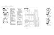
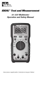
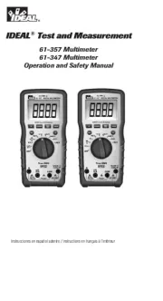
Ideal 61-342 Manual

Ideal Multimeter 61-342

Læs gratis den danske manual til Ideal 61-342 (6 sider) i kategorien Multimeter. Denne vejledning er vurderet som hjælpsom af 16 personer og har en gennemsnitlig bedømmelse på 4.9 stjerner ud af 8.5 anmeldelser. Har du et spørgsmål om Ideal 61-342, eller vil du spørge andre brugere om produktet?

Side 1/6
AC Voltage (V~)
#61-340
#61-342
Digital Multimeter
Instruction Manual
Read First: Safety Information
Understand and follow operating instructions
carefully. If this tester is not used in a manner
specified by IDEAL, protection provided by the
product may be impaired.
WARNINGS
To avoid possible electric shock, personal injury or
death follow these instructions:
Do not use if meter appears damaged.
Visually inspect the meter to ensure case is not
cracked and back case is securely in place.
Inspect and replace leads if insulation is dam-
aged, metal is exposed, or probes are cracked.
Pay particular attention to the insulation sur-
rounding the connector.
Do not use meter if it operates abnormally as
protection maybe impaired.
Do not use during electrical storms or in wet
weather.
Do not use around explosive gas, dust, or vapor.
Do not apply more than the rated voltage to the
meter.
Do not use without the battery and the back case
properly installed.
Remove the test leads from the meter before
removing battery cap.
Do not attempt to repair this unit as it has no
user-serviceable parts.
Disconnect power and discharge capacitors
before testing resistance, continuity, diodes,
capacitance or temperature.
Replace battery as soon as low battery indicator
appears to avoid false readings.
Use the proper terminals, function and range for
your measurements.
Comply with local and national safety
requirements, including the use of appropriate
personal protective equipment.
CAUTION:
To protect yourself, think "Safety First":
Voltages exceeding 30VAC or 60VDC pose a
shock hazard so use caution.
Use appropriate personal protective equipment
such as safety glasses, face shields, insulating
gloves, insulating boots, and/or insulating mats.
Before each use:
- Perform a continuity test by touching the
test leads together to verify the functionality
of the battery and test leads.
- Use the 3 Point Safety Method. (1) Verify
meter operation by measuring a known
voltage. (2) Apply meter to circuit under
test. (3) Return to the known live voltage
again to ensure proper operation.
Never ground yourself when taking electrical
measurements.
Connect the black common lead to ground or
neutral before applying the red test lead to
potential voltage. Disconnect the red test lead
from the voltage first.
Always work with a partner.
When using the probes, keep fingers as far
behind the probe tips as possible.
Ranges & Accuracies:
AC Converter: 61-340 model is averaging
sensing, rms calibrated; 61-342 model is true rms
sensing.
Accuracy: Accuracy is specified as +/-(a
percentage of the reading + a fixed amount) at
23°C±5°C (73.4°F ± 9°F), less than 75% relative
humidity.
Temperature Coefficient: 0.1 times the
applicable accuracy specification from 32°F to
64°F and 82°F to 122°F (0°C to 18°C ; 28°C to
50°C).
Ranges & Accuracies
DC Voltage (V )
DC
+
Toggle for
Frequency
(>20% of
range)
Function Range & Resolution Accuracy Overload Protection
DC Voltage 400.0m/4.000/40.00/400.0 V ±(0.5%+5)
600.0V ±(1.0%+3)
AC Voltage 400.0m/4.000/40.00/400.0/600 V ±(1.5%+5)
(40~400Hz)
DC Current 400.0/4000 µA ; 40.00/400.0 mA ±(0.5%+5) 500mA/600V Fast Fuse
4.000/10.00 A ±(1.5%+5) 10A/1000V Fast Fuse
AC Current 400.0/4000 µA ±(1.5%+5) 500mA/600V Fast Fuse
(40~400Hz) 40.00/400.0 mA ±(2.0%+5)
4.000/10.00 A ±(2.5%+5) 10A/1000V Fast Fuse
400.0 ±(1.2%+5)
Resistance 4.000k/40.00k/400.0k ±(1.0%+2) 600V DC/AC rms
4.000M±(1.2%+2)
40.00M±(2.0%+5)
40.00nF ±(3.0%+10)
Capacitance* 400.0n/4.000µ/40.00µ F ±(3.0%+5) 600V DC/AC rms
400.0µ/4000µ F ±(20%+5)
Frequency 10.00/100.0/1.000k/10.00k/100.0k/1.000M/10.00M Hz ±(0.1%+3) 600V DC/AC rms
Sensitivity: <1MHz: 0.7Vrms ; >1MHz: 5Vrms
Duty Cycle 0.1 - 99.9% ±(2.5%+5) (<10kHz)
Diode Check Test current : (1±0.6) mA and then open circuit voltage is 2.5VDC typical. 600V DC/AC rms
Continuity The beeper turns on <25 and turns off at >120 . 600V DC/AC rmsΩ Ω
Temperature** -58~1500°F ±(3.0%+5)
-50~800°C ±(3.0%+3)
*Accuracy not available for <10nF capacitance. **Accuracy is stated for meter only. Thermocouple accuracy adds another ±2.5% to reading.
Input Impedance : 10M for VAC & VDC. CF > 2, add ±1.0% to accuracy.
900VDC
750VAC rms
+
~
Symbols
Risk of electric shock
See instruction card
DC measurement
Equipment protected by double or
reinforced insulation
Battery
Earth
AC measurement
Conforms to EU directives
ND 6447-1 61-340 61-342 Ins 3/17/08 6:42 AM Page 1
Hz
AC/DC Current (A ) Specifications
General Features
Display: 3999 Count LCD / 3-3/4 Digit
Refresh Rate: 2.5x/sec.
Over range: “OL” is displayed
Polarity: Automatic (no indication for
positive polarity); Minus(-) sign
for negative polarity
True-RMS: 61-342 only.
Auto Power Off: After 10 minutes of non-use
Low Battery: is displayed if battery voltage
drops below operating voltage
Altitude: 6561.7 ft. (2000m)
Accuracy: Stated accuracy at 73° ±41°F
(23° ±5°C), < 75% R.H.
Batteries: 9VDC NEDA 1604
Battery Life: 200 hrs. (61-340)
150 hrs. (61-342)
Fuse: 0.5A/500V (#F-340)
10A/1000V (#F-341)
Operating 32° to 104°F (0° to 40°C)
environment: at < 75% R.H.
Storage -4° to 140°F (-20° to 60°C)
environment: at < 80% R.H.
Weight: 13.6 oz (386g)
Size: 7.0"H x 3.5"W x 1.9"D
(177mmHx89mmWx48mmD)
Accessories Test leads (TL-310), 9V battery,
Included: Operating Instructions
Safety Complies with UL/IEC/EN 61010-1,
Certification: 61010-031, Cat III-600V
Equipment protected by double
insulation.
Instrument has been evaluated and complies with
insulation category III (overvoltage category III) for
measurements performed in the building installation.
Pollution degree 2 in accordance with IEC-644.
Indoor use.
C US
N12966
+
Maintenance
Clean the case with a damp cloth and mild deter-
gent. Do not use abrasives or solvents.
Service and Replacement
Parts
No user-serviceable parts.
For replacement parts or to inquire about service
information contact IDEAL INDUSTRIES, INC. at
1-877-201-9005 or visit our website @
www.testersandmeters.com.
Warranty Statement
This tester is warranted to the original purchaser
against defects in material and workmanship for
two years from the date of purchase. During this
warranty period, IDEAL INDUSTRIES, INC. will, at
its option, replace or repair the defective unit, sub-
ject to verification of the defect or malfunction.
This warranty does not cover fuses, batteries or
damage from abuse, neglect, accident, unautho-
rized repair, alteration, or unreasonable use of the
instrument.
Any implied warranties arising out of the sale of an
IDEAL product, including but not limited to implied
warranties of merchantability and fitness for a par-
ticular purpose, are limited to the above. The man-
ufacturer shall not be liable for loss of use of the
instrument or other incidental or consequential
damages, expenses, or economic loss, or for any
claim or claims for such damage, expenses or eco-
nomic loss.
State laws vary, so the above limitations or exclu-
sions may not apply to you. This warranty gives
you specific legal rights, and you may also have
other rights which vary from state to state.
DC A
Closed
Circuit
Open
Circuit
Ω
WARNING: To avoid electric shock, dis-
connect test leads before removing battery cover.
WARNING: For continued protection
against fire, replace only with fuses of the speci-
fied voltage, current and rupture speed ratings.
Bad Diode
Good Diode
Open Shorted
Foward Reverse
Diode Test ( ) Frequency (Hz) /
Duty Cycle(%)
WARNING: De-energize circuit first.
WARNING: De-energize circuit before
checking diode.
Note: On noisy circuits, turn dial to V, then
toggle Hz button.
WARNING: To avoid electric shock, do
not place test leads or thermocouple on a
voltage source.
~
Toggle for
AC
Toggle for
Hz
Toggle for
)))
Toggle for
(Remove t ilt st and)
Audible Continuity (
))))
+
Temperature
Data Hold
Hold
Press to hold
present value in
display; depress to
release display.
Min/Max
Relative Mode
Toggle for
Relative Mode
Press to deduct
reference value;
depress to exit
mode.
Backlight
Press >1 sec.
for backlight ( )
Backlight stays
illuminated for
10 sec.
Range
Toggle to manual
range on following
functions: Volts,
Ohms, Amps.
Hold for >1sec. to
exit mode.
Turn power off, break circuit, insert meter in
series, then turn power back on.
WARNINGS:
Check fuse for continuity before testing.
Use the proper switch position and lead
inputs.
Never attempt to measure current on
circuits or equipment with more than
600 volts potential.
Duty cycle: 15sec ON / 15min OFF for
10A MAX
Toggle for
°C
Toggle for
Duty Cycle
Toggle for
Min/Max
Hold for >1sec.
to exit mode.
MAX MIN
Capacitance ( )
nF
WARNING: De-energize circuit before
taking resistance measurement.
WARNING: De-energize circuit and
discharge capacitor before taking capaci-
tance measurement.
Measuring time: < 15sec for <400µF
< 1min for <4000µF
MΩ
Resistance ()
Toggle for Battery & Fuse Replacement
~
ND 6447-1 61-340 61-342 Ins 3/17/08 6:42 AM Page 8


Produkt Specifikationer

Mærke: Ideal
Kategori: Multimeter
Model: 61-342

Har du brug for hjælp?

Hvis du har brug for hjælp til Ideal 61-342 stil et spørgsmål nedenfor, og andre brugere vil svare dig


Multimeter Ideal Manualer

Ideal

Ideal 61-342 Manual

27 December 2024
Ideal

Ideal 61-337 Manual

21 August 2024
Ideal

Ideal 61-357 Manual

17 August 2024

Multimeter Manualer

Nyeste Multimeter Manualer

Draper

Draper 52320 Manual

8 Juni 2025
VOREL

VOREL 81780 Manual

7 Juni 2025
Brymen

Brymen BM878 Manual

7 Juni 2025
Brymen

Brymen BM789 Manual

6 Juni 2025
Draper

Draper 16232 Manual

6 Juni 2025
Draper

Draper 41822 Manual

6 Juni 2025
Draper

Draper 41820 Manual

6 Juni 2025
Brymen

Brymen BM805s Manual

6 Juni 2025
Brymen

Brymen BM785 Manual

6 Juni 2025
Brymen

Brymen BM239R Manual

3 Juni 2025