Inkbird ITC-100 Manual
Inkbird
Temperaturregulator
ITC-100

| Mærke: | Inkbird |
| Kategori: | Temperaturregulator |
| Model: | ITC-100 |
Har du brug for hjælp?
Hvis du har brug for hjælp til Inkbird ITC-100 stil et spørgsmål nedenfor, og andre brugere vil svare dig
Temperaturregulator Inkbird Manualer
30 September 2025
29 September 2025
8 Juli 2025
8 Juli 2025

8 Juli 2025

20 Juli 2024

8 Juli 2024

7 Juli 2024
Temperaturregulator Manualer
- Festo
- Ventus
- Atag
- Dimplex
- JUNG
- Panasonic
- Carel
- Bulex
- Fluke
- Mueller
- ACV
- Protector
- AEG
- Fantini Cosmi
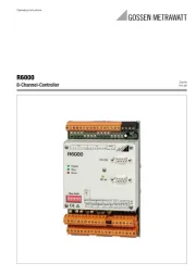
- Gossen Metrawatt
Nyeste Temperaturregulator Manualer

30 November 2025
26 September 2025
7 September 2025
3 September 2025
2 September 2025
18 August 2025
18 August 2025
11 August 2025
11 August 2025
9 August 2025