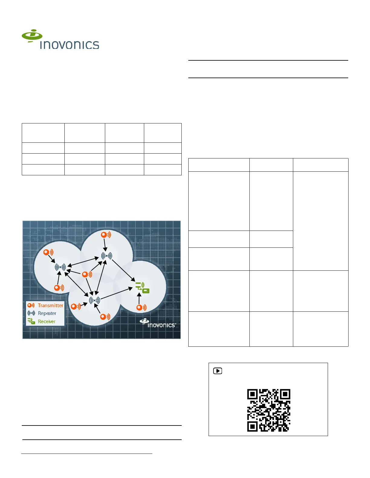
2/3/20 357-05637-02 Rev A © Inovonics, 2020 - www.inovonics.com 2
• E-mail: support@inovonics.com.
• Phone: (800) 782-2709; (303) 939-9336.
1.4 EN4216MR Front Panel
Figure 2 Receiver front panel
Output LED: Lights when any transmitter output is active.
Fault LED: Lights when any transmitter is sending a fault condition.
Power LED: Lit when receiving power.
LCD Display: Shows status, event log and programming information.
Decode LED: Flashes when any recognizable transmission is received.
This LED is only visible when the cover is removed.
Up button: Scrolls the display up.
Down button: Scrolls the display down.
Back button: Returns display to the previous menu, or when pressed in the
main menu options, returns the unit to normal operating mode. When
entering information in the display, returns to the last character entered.
Enter button: Selects the currently displayed menu item. If in normal
operating mode, sets the unit to menu mode.
Reset button: Clears the current status for all points and resets all outputs
and LEDs. Records a receiver reset entry in the event log and resets the
supervision window timers. This button is only accessible when the cover is
removed.
1.5 EN4216MR Internal Components
Figure 3 EN4216MR internal components
1.6 What’s in the Carton
• Two drywall anchors.
• Two mounting screws.
• Two pieces of double-sided mounting tape.
• One selection jumper.
2 Installation and Startup
2.1 Installation Notes
• These products are designed to be maintained by professional
security technicians.
• Products are tested for indoor use.
• Do not mount wireless smoke detectors, co detectors, initiating device
transmitters or repeaters to removable surfaces, such as ceiling tiles.
• All products should be manually tested weekly.
• The EN4216MR must be installed within 30 m (98.5 ft) of control unit.
• Low power transmitters shall be limited to a single initiating device.
2.2 Power Cabling
Caution: Incorrect connections may cause damage to the unit.
Before beginning startup, you will need to connect power to the receiver. To
connect power to the receiver:
1. Use a small screwdriver to press the housing release tabs on the top or
bottom of the receiver; separate the housing.
2. Connect power cabling to the Vs (+) and GND (-) connections.
• Power source should be 11-14 VDC. Power supply must be
unswitched, uninterrupted, and regulated.
• Use 18 - 22 gauge wire for all cabling, and ensure torque on the screw
terminals does not exceed 7 inch-pounds.
2.3 Select the Frequency Band
EchoStream products are able to use a range of radio frequencies, and are
shipped from Inovonics set for your geographic area.
• The jumper will be set on the two pins marked NZ to set the frequency
range to 921-928 MHz for New Zealand.
• The jumper will be set on the two pins marked AU to set the frequency
range to 915-928 MHz for Australia.
• The jumper will be removed to set the frequency band to 902-928
MHz for North America.
1. Ensure the frequency band is set for your geographic are.
2. If the frequency band is not set for your geographic area, place a
selection jumper on the appropriate frequency band selection pins to
select Australia or New Zealand, or remove it for North America.
Note: Only devices set for use in North America are configured for UL
installations.
3. If you have changed the frequency band and the device is powered on,
press the reset button to complete configuration.
2.4 Connect Input/Output Cabling
4. Connect cabling to the receiver power loss output. Must be configured
for UL installations.
• The receiver power loss output is a normally closed (N/C) open
collector output that opens when the receiver loses power.
5. Connect cabling to the tamper output. Must be configured for UL
installations.
• The tamper output is a normally open (N/O) open collector output that
reports receiver case tamper to an external device.
6. Connect cabling to the jam output. Must be configured for UL
installations.
• The jam output is a normally closed (N/C) open collector output that
opens when noise thresholds on all receive channels remain above a
predetermined value for 10 seconds. The jam output is set to the
follower output type.
7. Connect a momentary switch to the reset input and ground (Figure 4,
“EN4216MR terminals”). Must be configured for UL installations.
• The reset input circuit permits installation of a remote momentary
normally open (N/O) switch to clear faults, unlatch outputs, and reset
the receiver to a normal state.
8. Connect cabling to the output terminals. Must be configured for UL
installations.
• The EN4216MR provides six Form-C relays.
Figure 4 EN4216MR terminals
A B COutput LED Fault LED Power LED
D E FLCD display Up button Down button
G HBack button Enter button
AHousing release
tabs
BPower
connections
COperation LEDs
D ERelay outputs Tamper output FReceiver power loss output
G H IJam output Reset input Frequency band selection
pins
J KReset button Decode LED