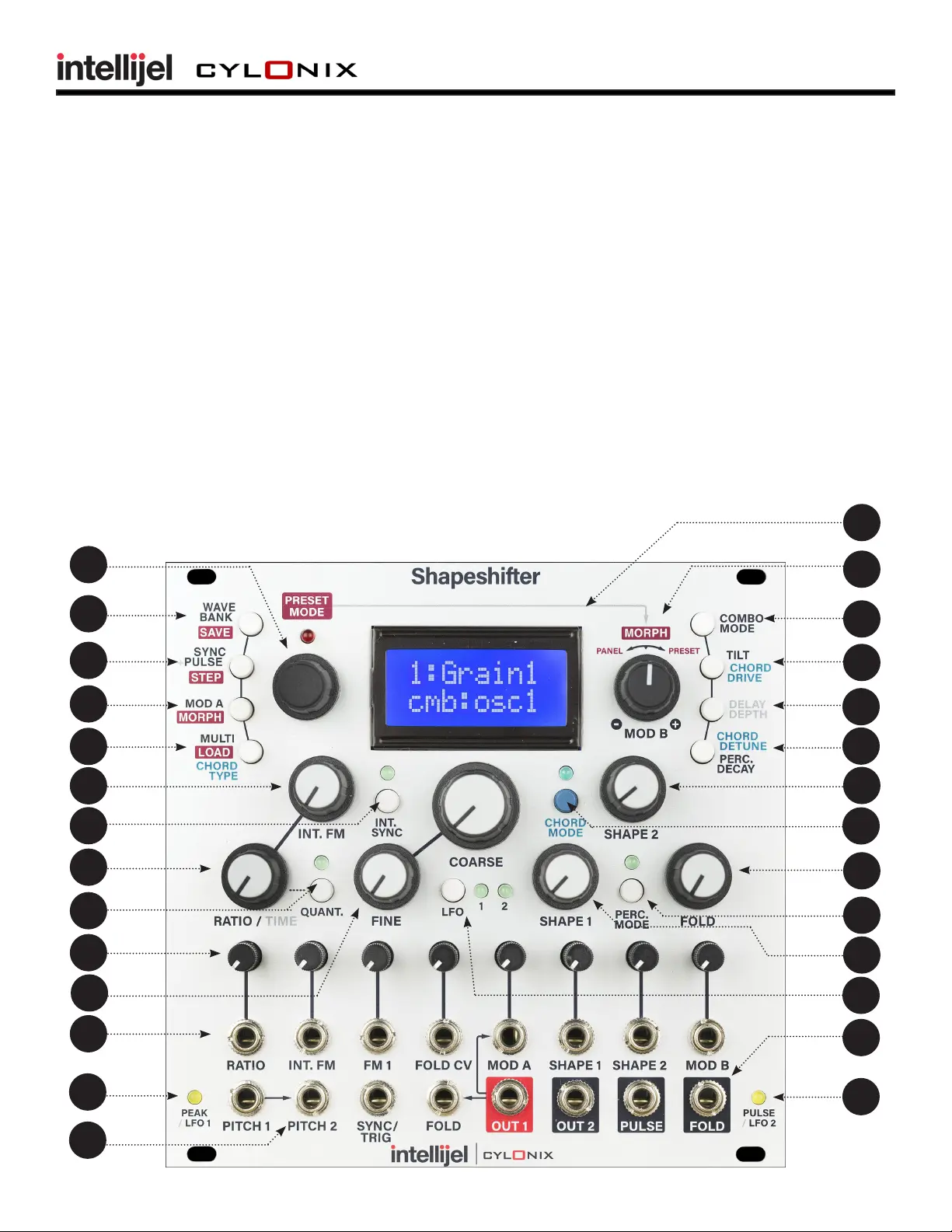
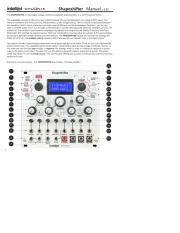
Intellijel Shapeshifter Manual

Intellijel Tastatur Shapeshifter

Læs gratis den danske manual til Intellijel Shapeshifter (25 sider) i kategorien Tastatur. Denne vejledning er vurderet som hjælpsom af 3 personer og har en gennemsnitlig bedømmelse på 3.9 stjerner ud af 2 anmeldelser. Har du et spørgsmål om Intellijel Shapeshifter, eller vil du spørge andre brugere om produktet?

Side 1/25
1
The SHAPESHIFTER is a dual digital voltage controlled wavetable-based oscillator in a 26-HP Eurorack format.
The wavetables consists of 128 banks, each with 8 individual 512-sample waveforms, for a total of 1024 waves. The
choice of waveform within the currently selected bank is under voltage control. There is smooth interpolaon between
the waveforms within a bank, allowing a very wide range of dierent possible waveshapes. Oscillator 1 can be oper-
ated in a CHORD mode, which runs 8 copies of the oscillator in parallel with adjustable detuning, leading to very fat, rich
waveforms. The oscillators have extensive modulaon capabilies including audio rate (98KHz) Frequency and Phase
Modulaon (FM and PM) via external sources. Nonlinear combinaon processes allow the outputs of the two oscillators
to interact to generate complex mbres and sonic textures. The SHAPESHIFTER module also includes the analog wave
folder circuitry from the intellijel mFold II module to add analog warmth and metallic rasps to the digital output.
The module includes a sophiscated preset mode where panel sengs can be stored. There are 100 user-prgrammable
preset memory slots. The capabilies of the preset mode is not limited to mere passive storage of sengs, however. In
this mode the user can also step through, or sequence, the sengs, either in order or randomly in response to pulses
input to the external sync input. This gives the user the ability to generate complex sequences of sounds. The preset
mode also allows the user to morph between the current panel sengs and a preset providing a very powerful real-me
performance tool.
But, there is one more thing ... the SHAPESHIFTER also includes a 64-band vocoder!
15
Active Scale
Shapeshier Manual v 2.03
1
2
3
4
5
7
6
8
9
10
12
Active Scale
14
15
16
17
18
23
24
25
11
19
20
22
21
26
13
27
28
2 3
Front Panel Elements (numbers refer to the diagram on the rst page)
MANUAL DATA INPUT - this is a rotary encoder which is used to enter data in various operaon modes.
Pushing on the encoder acvates a switch which enters and exits the PRESET mode. The red LED above
the encoder indicates whether or not the PRESET mode is acve. When the LED is lit the PRESET mode is
acve.
WAVE BANK/SAVE BUTTON - this buon, when pressed, switches the rotary encoder to entry of the
acve wave bank for oscillator 1 or 2. Successive presses of the buons toggles between oscillator 1 and
oscillator 2. When bank select is acve, the top line of the LCD display will show a descripve tle for
the currently selected wave bank. The waves corresponding to each wave bank are depicted in Appendix
A. When the module is in PRESET mode (indicated by the illuminaon of the red LED above the rotary
encoder) this buon has a dierent funcon - that of saving the current front panel control state into
the currently selected preset.
SYNC/PULSE/STEP BUTTON - this buon, when pressed, switches the rotary encoder to selecon of the
oscillator 1 SYNC mode. A second press leads to seng of the oscillator 2 SYNC mode. A third press of
the buon switches the rotary encoder to selecon of the PULSE output source.
When the module is in PRESET mode (indicated by the illuminaon of the red LED above the rotary en-
coder) this buon has a dierent funcon - that of entering the PRESET STEP mode.
MODA/MORPH BUTTON - this buon, when pressed, switches the rotary encoder to selecon of the
MODA desnaon. When pressed a second me, the encoder is used to select whether the OSC2 out-
put modulaons the SHAPE1 or TILT parameters.
When the module is in PRESET mode (indicated by the illuminaon of the red LED above the rotary en-
coder) this buon has a dierent funcon - that of entering the MORPH mode.
CHORD TYPE/MULTI/LOAD BUTTON - this buon, when pressed, switches the rotary encoder to selec-
on of the MULTI seng for oscillator 1. A second press of the buon switches the rotary encoder to
selecon of the MULTI seng for oscillator 1. If CHORD mode is acve (as indicated by the illuminaon
of the LED above the CHORD mode buon) then a third buon press will switch the rotary encoder to
selecon of the CHORD type.
When the module is in PRESET mode (indicated by the illuminaon of the red LED above the rotary
encoder) this buon has a dierent funcon - that of loading the control sengs from the currently
selected PRESET.
INT. FM POTENTIOMETER - this potenometer provides an oset that is summed with the external IFM
input signal to produce the signal that sets the modulaon of oscillator 1’s frequency by the output of
oscillator 2. The internal FM is computed at the system clock rate of 25 MHz, providing very high-quality
aliasing free modulaons.
INT. SYNC BUTTON - this buon toggles the internal sync on and o. When on, as indicated by the il-
luminaon of the LED above the buon, both oscillators 1 and 2 are synchronized at the start of each
cycle of an internal synchronizaon oscillator running at the same frequency as oscillator 1 (except that
the synchronizaon oscillator is not aected by the FM inputs to oscillator 1). The specic response of
the oscillators to the synchronizaon pulses depends on the SYNC mode seng. Pressing the buon
twice will cause the LED to ash, and the internal synchronizaon oscillator will then run at half the
frequency of oscillator 1.
1
2
3
4
5
7
6
8
9
10
12
11
13
Front Panel Elements (connued...)
RATIO/TIME POTENTIOMETER - this potenometer provides an oset to the oscillator 2 RATIO seng.
This is summed with the external RATIO input signal. The pitch of oscillator 2 is shied by an amount
proporonal to this sum. Oscillator 2’s frequency seng is also used to set the delay me for the echo
eect, thus the RATIO/TIME potenometer can be used to alter the delay me.
QUANT. BUTTON - this buon, when pressed, toggles quanzaon of the oscillator 2 frequency rao on
and o. When rao quanzaon is enabled the pitch of oscillator 2 is ed directly to the pitch of oscilla-
tor 1. The external PITCH2 input is ignored in this situaon. There are 16 dierent quanzed raos avail-
able: [1/8, 3/16, 1/4, 5/16, 3/8, 1/2, 5/8, 3/4, 1, 5/4, 3/2, 2, 3, 4, 6, 8]. Pressing the buon twice when
oscillator 2 is in LFO mode puts the system into a mode where the PITCH2 input becomes a clock input,
and the frequency of oscillator 2 follows the frequency of the clock input.
MODULATION INPUT ATTENUATORS - these mini-potenometers (without knobs) serve to adjust the
level of the modulaon inputs (those from the second row of jacks from the boom of the front panel).
FINE and COARSE POTENTIOMETERS - these two potenometers provide an oset to the pitch for both
oscillators. This oset is summed with the external pitch input signals (PITCH1 and PITCH2), as well as
the RATIO signal in the case of oscillator 2, to produce the oscillator pitches.
MODULATION INPUT JACKS - the top row of jacks are used to input eight dierent modulaon signals.
These signals include:
RATIO: adjusts the rao of the frequency of oscillator 2 as compared to that of oscillator 1.
IFM: sets the level of the internal frequency modulaon of oscillator 1 by oscillator 2.
FM 1: audio rate linear frequency modulaon of oscillator 1.
FOLD CV: adjusts the amount of waveform folding imposed by the analog wave folder.
MOD A: audio rate modulaon input with a number of dierent modulaon targets.
SHAPE 1: modulates the shape of oscillator 1’s waveform within the current wavetable bank.
SHAPE 2: modulates the shape of oscillator’ 2s waveform within the current wavetable bank.
MOD B: low rate modulaon input with a number of dierent modulaon targets.
PEAK/LFO 1 LED - this LED indicates whether either of the two audio-rate modulaon inputs, FM 1 and
MOD A, have reached the limits of their range, and hence whether clipping of these signals is occuring.
If you see the PEAK LED come on, turn down the aenuator for these inputs. When oscillator 1 is op-
erang in LFO mode, this LED no longer signals the presence of peaks, but instead indicates the sign of
output 1 (i.e. the LED is illuminated whenever output 1 is posive).
INPUT JACKS - the four lemost jacks in the boom row are used to input the following signals:
PITCH 1: this input sets the pitch of oscillator 1. It has a 1 volt/octave scale factor.
PITCH 2: this input sets the pitch of oscillator 2. It has a 1 volt/octave scale factor. This jack is
normalized to the PITCH 1 jack, which means that if no cable is plugged into the PITCH 2 jack, the PITCH
2 input follows the signal input to the PITCH 1 jack.
SYNC: posive-going pulses input to this jack cause the oscillators to be synchronized, according
to the current SYNC mode sengs. These pulses are also used to trigger the percussive aacks when
the module is in PERC mode, and cause stepping of the presets when preset stepping is acvated.
FOLD IN: the signal input to this jack is fed to the input of the analog wavefolder circuitry. It is
normalized to the OUT 1 jack, so that if no cable is plugged into the FOLD IN jack, the input to the wave-
folder is taken from output 1.
14


Produkt Specifikationer

Mærke: Intellijel
Kategori: Tastatur
Model: Shapeshifter

Har du brug for hjælp?

Hvis du har brug for hjælp til Intellijel Shapeshifter stil et spørgsmål nedenfor, og andre brugere vil svare dig


Tastatur Intellijel Manualer

Intellijel

Intellijel Tangrams Manual

6 September 2025
Intellijel

Intellijel XFADE 1U Manual

6 September 2025
Intellijel

Intellijel SVF 1U Manual

6 September 2025
Intellijel

Intellijel Shifty Manual

6 September 2025
Intellijel

Intellijel Stomp Manual

6 September 2025
Intellijel

Intellijel Polaris Manual

6 September 2025
Intellijel

Intellijel µMIDI Manual

6 September 2025

Tastatur Manualer

Nyeste Tastatur Manualer

Xcellon

Xcellon KBM-A2USG Manual

5 September 2025
Yamaha

Yamaha SC-Genos Manual

2 September 2025
Cougar

Cougar Puri RGB Manual

2 September 2025
Gamesir

Gamesir GK300 Manual

31 August 2025
Gamesir

Gamesir Z2 Manual

31 August 2025
Auray

Auray PBM-HYD-19 Manual

31 August 2025
AKAI

AKAI MPC Key 37 Manual

30 August 2025
ModeCom

ModeCom MC-5006 Manual

29 August 2025