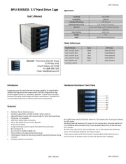
IStarUSA BPU-350SATA-KL Manual
Læs gratis den danske manual til IStarUSA BPU-350SATA-KL (2 sider) i kategorien Disk array. Denne vejledning er vurderet som hjælpsom af 9 personer og har en gennemsnitlig bedømmelse på 4.7 stjerner ud af 5 anmeldelser.
Har du et spørgsmål om IStarUSA BPU-350SATA-KL, eller vil du spørge andre brugere om produktet?
Produkt Specifikationer
| Mærke: | IStarUSA |
| Kategori: | Disk array |
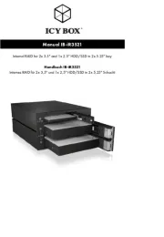
| Model: | BPU-350SATA-KL |
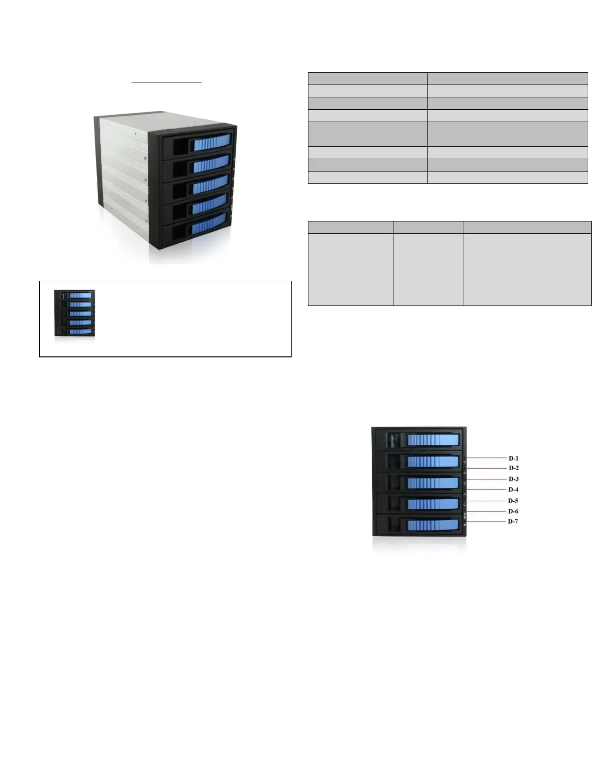
| Bredde: | 146 mm |
| Dybde: | 209.5 mm |
| Højde: | 126 mm |
| Produktfarve: | Sort |
| Kabler inkluderet: | SATA |
| Bæredygtighedscertifikater: | RoHS |
| Intern: | Ja |
| Antal blæsere: | 1 blæser(e) |
| Grænseflade til lagerdisk: | Serial ATA, Serial ATA II, Serial ATA III |
| Størrelse på lagerdisk: | 2.5/3.5 " |
| Understøttet datalagringsdrev typer: | HDD & SSD |
| Antal understøttede lagerdiske: | 5 |
| Datalagringsdriver installeret: | Ingen |
| Dataoverførselshastighed: | 6 Gbit/sek. |
| Kabinettype: | Desktop |
| Installeret lagerdisktype: | Ingen |
| Total installeret opbevaringskapacitet: | - TB |
| Maksimalt understøttet lagerkapacitet: | - TB |
| RAID-niveauer: | JBOD |
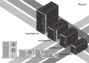
| Hot-swap drevbåse: | Ja |
| Værtsporte: | 5 |
| SATA-værtport: | Ja |
Har du brug for hjælp?
Hvis du har brug for hjælp til IStarUSA BPU-350SATA-KL stil et spørgsmål nedenfor, og andre brugere vil svare dig
Disk array IStarUSA Manualer


Disk array Manualer
- OWC
- Ibm
- Addonics
- Intel
- HP
- Icy Dock
- Infortrend
- QNAP
- Silverstone
- CRU
- Western Digital
- Glyph
- Buffalo
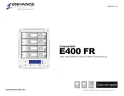
- Enhance
- Quantum
Nyeste Disk array Manualer