Johnson Control T600MEP-3 Manual


Læs gratis den danske manual til Johnson Control T600MEP-3 (17 sider) i kategorien Termostat. Denne vejledning er vurderet som hjælpsom af 36 personer og har en gennemsnitlig bedømmelse på 4.7 stjerner ud af 18.5 anmeldelser. Har du et spørgsmål om Johnson Control T600MEP-3, eller vil du spørge andre brugere om produktet?

Side 1/17
T600MEP-3 Multi-stage Economizer Thermostat Installation Instructions 1
Applications
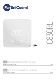
The T600MEP-3 programmable thermostats are
specifically designed for control of rooftop units with
economizers.
North American Emissions Compliance
United States
This equipment has been tested and found to comply
with the limits for a Class A digital device pursuant to
Part 15 of the FCC Rules. These limits are designed to
provide reasonable protection against harmful
interference when this equipment is operated in a
commercial environment. This equipment generates,
uses, and can radiate radio frequency energy and, if
not installed and used in accordance with the
instruction manual, may cause harmful interference to
radio communications. Operation of this equipment in a
residential area is likely to cause harmful interference,
in which case the user will be required to correct the
interference at his/her own expense.
Canada
This Class (A) digital apparatus meets all the
requirements of the Canadian Interference-Causing
Equipment Regulations.
Cet appareil numérique de la Classe (A) respecte
toutes les exigences du Règlement sur le matériel
brouilleur du Canada.
Installation
Location Considerations
Locate the T600MEP-3 thermostat:
on a partitioning wall, approximately 5 ft (1.5 m)
above the floor in a location of average
temperature
away from direct sunlight, radiant heat, outside
walls, behind doors, air discharge grills, stairwells,
or outside doors
away from steam or water pipes, warm air stacks,
unconditioned areas (not heated or cooled), or
sources of electrical interference
Note: Allow for vertical air circulation to the
T600MEP-3 thermostat.
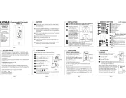
To install the thermostat:
1. Use a Phillips-head screwdriver to remove the
security screw on the bottom of the thermostat
cover.
2. Pull the bottom edge of the thermostat cover and
open the thermostat as illustrated in Figure 1.
IMPORTANT: The T600MEP-3 Thermostat is
intended to provide an input to equipment under
normal operating conditions. Where failure or
malfunction of the thermostat could lead to personal
injury or property damage to the controlled
equipment or other property, additional precautions
must be designed into the control system.
Incorporate and maintain other devices such as
supervisory or alarm systems or safety or limit
controls intended to warn of or protect against failure
or malfunction of the thermostat.
Figure 1: Removing the Thermostat Cover
FIG:cvr_rmvl
T600MEP-3 Multi-stage Economizer Thermostat
Installation Instructions
T600MEP-3 Part No. 24-9890-609, Rev. —
Issued September 20, 2006
T600MEP-3 Multi-stage Economizer Thermostat Installation Instructions2
3. Carefully pull the locking tabs on the right side of
the thermostat mounting base and unlock the
Printed Circuit Board (PCB). Open the PCB to the
left as illustrated in Figure 2.
4. Pull approximately 6 in. (152 mm) of wire from the
wall and insert the wire through the hole in the
thermostat mounting base.
5. Align the thermostat mounting base on the wall and
use the base as a template to mark the two
mounting hole locations.
Note: Be sure to position the thermostat mounting
base so that the arrow on the base points upward to
indicate the top of the thermostat.
6. Drill a 3/16 in. (5 mm) hole at each of the two
marked locations and tap nylon anchors (included
with the thermostat) flush to the wall surface.
7. Position the thermostat mounting base on the wall
and use the two mounting screws (included with
the thermostat) to secure the base to the surface
as illustrated in Figure 3.
Note: Be careful not to overtighten the mounting
screws.
8. Swing the PCB back to the right and carefully snap
it into the locking tabs on the thermostat mounting
base.
9. Pull the pull-tabs on each of the connectors and
remove the screw terminal blocks as illustrated in
Figure 4.
Wiring
When an existing thermostat is replaced, remove and
label the wires to identify the terminal functions. When
a T600MEP-3 thermostat is replaced, simply remove
the old screw terminal blocks and reinsert them onto
the PCB of the replacement thermostat.
Figure 2: Opening the Thermostat PCB
FIG:prntd_crct_brd
PCB
Locking
Tabs
Figure 3: Securing the Thermostat
Mounting Base to the Wall
FIG:mntng_bs
!
CAUTION: Risk of Electric Shock.
Disconnect power supply before making
electrical connections to avoid electric
shock.
!
CAUTION: Risk of Property Damage.
Do not apply power to the system before
checking all wiring connections. Short
circuited or improperly connected wires
may result in permanent damage to the
equipment.
IMPORTANT: Make all wiring connections in
accordance with local, national, and regional
regulations. Do not exceed the electrical ratings of
the T600MEP-3 thermostat.
Figure 4: Removing the Screw Terminal Blocks
FIG:trmnl_blcks


Produkt Specifikationer

Mærke: Johnson Control
Kategori: Termostat
Model: T600MEP-3

Har du brug for hjælp?

Hvis du har brug for hjælp til Johnson Control T600MEP-3 stil et spørgsmål nedenfor, og andre brugere vil svare dig


Termostat Johnson Control Manualer

Termostat Manualer

Nyeste Termostat Manualer

Finder

Finder 1T.T1 Manual

4 Juli 2025
Honeywell

Honeywell X2P Manual

1 Juli 2025
Honeywell

Honeywell X1N Manual

29 Juni 2025
Honeywell

Honeywell X2S Manual

29 Juni 2025
MKC

MKC MK-683 Manual

21 Juni 2025
Maginon

Maginon WT-2G Manual

21 Juni 2025
MKC

MKC MKTIW-1 Manual

20 Juni 2025
MKC

MKC TH-555C Manual

19 Juni 2025