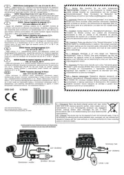
Kemo M195 Manual

Kemo Legetøj M195

Læs gratis den danske manual til Kemo M195 (4 sider) i kategorien Legetøj. Denne vejledning er vurderet som hjælpsom af 29 personer og har en gennemsnitlig bedømmelse på 4.5 stjerner ud af 15 anmeldelser. Har du et spørgsmål om Kemo M195, eller vil du spørge andre brugere om produktet?

Side 1/4
DE M195 | PWM Leistungsregler
9 - 28 V/DC, max. 20 A
Leistungsregler zum Regeln von Gleichspannungslasten
(Gleichstrommotoren, Glühlampen, Heizungen, LEDs mit Vor-
widerständen usw.). Durch die verwendete PWM (Impulsbrei-
ten)-Steuerung laufen Elektromotoren auch bei kleinen Dreh-
zahlen gut an. Schaltfrequenz: ca. 300 - 600 Hz (bei Motoren
kann ein Brummgeräusch hörbar sein).
Die Regelung erfolgt über das mitgelieferte Potentiometer oder
auch wahlweise mit einer externen Steuerspannung 0 - 5 V/DC.
EN M195 | PWM Power control
9 - 28 V/DC, max. 20 A
Power controller for controlling DC loads (DC motors, light bulbs,
heaters, LEDs with current limiting resistors, etc.). The use of
PWM (pulse width) control works well even with electric motors
running at low RPM. Switching frequency: approx. 300 - 600 Hz
(for motors, a humming noise may be heard).
The control is via the supplied potentiometer or optional with an
external control voltage 0 to 5 V/DC.
CZ M195 | Výkonový regulátor
9 - 28 V/DC max. 20 A (PWM)
Regulátor výkonu pro kontrolu zatížení DC (DC motory, žárovky,
topení, LED s sérioodpory, atd.). Který používá PWM (Pulse
Width) run-control elektromotory také dobré při nízkých rychlos-
tech. Spínací frekvence: 300 - 600 Hz (pro motory, může Hučení
slyšet).
Ovládání je pomocí dodávaného potenciometru nebo voli-
telného s externím řídicím napětím 0 - 5 V/DC.
ES M195 | Regulador de potencia
9 - 28 V/DC máx. 20 A (PWM)
Regulador de poder para controlar cargas DC (motores DC, lám-
paras, calentadores, LEDs con resistores de corriente limitados,
etc.). El uso del control PWM (anchuras de pulso) funciona muy
bien aún con los motores eléctricos trabajando con RPM bajas.
Frecuencia de conmutación: aprox. 300 - 600 Hz (en motores,
es posible percibir un ligero sonido de vibración).
El control de este se realiza via el potenciómetro incluido o con
un controlador de voltaje externo 0 a 5 V/DC.
FR M195 | Régulateur de puissance
9 - 28 V/DC max. 20 A (PWM)
Régulateur de puissance pour régler des charges de tension
continue (moteurs à courant continue, lampes à incandescen-
ce, chauffages, DEL avec résistances en série, etc.). Les mo-
teurs électriques démarrent bien aussi à une vitesse de rota-
tion plus basse par la commande PWM (largeur d’impulsions)
utilisée. Fréquence de commutation: env. 300 - 600 Hz (en cas
des moteurs un ronement peut être audible).
Le glage s’effectue par le potentiomètre inclus dans la livrai-
son, ou bien au choix par une tension de commande externe
de 0 - 5 V/DC.
IT M195 | Regolatore di potenza
9 - 28 V/DC max. 20 A (PWM)
Regolatore di potenza per regolare carici di tensione costan-
te (motori di tensione costante, lampade a incandescenza,
riscaldamenti, LED‘s con resistenza di polarizzazione, ecc.). Il
motore elettrico avvia meglio tramite il uso del modulatore PWM
ampiezza d‘impulso) anche in caso di piccoli numeri di giri.
Frequenza di operazioni: ca. 300 - 600 Hz (ché la possibilità di
sentire un ronzio a gli motori).
La regolazione avviene con il fornito potenziometro oppure con
una tensione di controllo esterna 0 - 5 V/DC.
NL M195 | Vermogensregelaar
9 - 28 V/DC max. 20 A (PWM)
Vermogens regelaar voor het regelen van gelijkspannings ap-
paraten (gelijkstroom motoren, gloeilampen, verwarming, led‘s
met voorschakel weeerstand etc.). Door de gebruikte PWM
(pulsbreedte) sturinglopen elektromotoren bij een klein toeren-
tal gelijkmatig. Schakelfrequentie: ca. 300 - 600 Hz (bij motoren
kan een kleine brom geluid hoorbaar zijn).
De regeling vind plaats via de bijgeleverde potmeter of naar
keuze met en externe stuurspanning 0 - 5 V/DC.
PL M195 | Regulator mocy PWM
9 - 28 V/DC max. 20 A
Regulator mocy do regulacji urządzeń na prąd stały (silniki,
żarówki, grzejniki, diody LED z szeregowym rezystorem i.t.d.).
Poprzez zastosowanie modulacji PWM (sterowanie szerokością
impulsów) silniki elektryczne pracują dobrze na małych obro-
tach. Częstotliwość pracy: ok. 300 - 600 Hz (może powodować
słyszalne buczenie przy regulacji silnikiem).
Do regulacji służy dołączony potencjometr lub do wyboru ze-
wnętrzne napięcie stałe 0 - 5 V/DC.
RU M195 | PWM Рeгулятор большой
мощности 9 - 28 Вольт, мaкс. 20 A
Модуль прeдстaвляeт собой рeгулятор большой мощности для
нaгрузок постоянного нaпряжeния (двигaтeли постоянного
токa, лaмпы нaкaливaния, приборы для отоплeния,
фотодиоды LED с прeдвaритeльным сопротивлeниeм и т.д.). С
примeнeниeм PWM (широтно–импульснмодуляциa) могут
двигaтeли хорошо рaботaть и нa низких оборотaх. Чaстотa
включeния приблизитeльно 300 - 600 Гц (у двигaтeлeй мож
появиться гудeниe).
Рeгуляция производится посрeдством потeнциомeтрa
который приклaдывaeтся к постaвкe, или по выбору с
помощью внeшнeго рeгулируeмого нaпряжeния 0 - 5 Вольт.
www.kemo-electronic.de
401180
1/4
P / Module / M195 / Beschreibung / 10040DI / Karton 1 (M195) / Ver.002
DE
Bestimmungsgemäße Verwendung:
Leistungsregelung von Gleichstrom-Verbrauchern wie Motoren, Lampen
usw.
Aufbauanweisung:
Das Modul kann sich, je nach Belastung, erwärmen. Es muss daher
an einer trockenen, gut belüfteten Stelle eingebaut werden. Bei
Belastungen von über 5 A (bis max. 20 A) muss das Modul mit der
Metall-Grundäche gekühlt werden. Das geschieht, indem es plan
auf einen hlkörper oder ein größeres Metallstück (z.B. Winkelprol,
Metallplatte) so angebaut wird, dass sich die Metall-Grundplatte des
Moduls bei höchster Belastung (die angeschlossene Last läuft mit max.
Leistung) nicht über +70°C erwärmt.
Die Betriebsspannung des Moduls muss zwischen 9 - 28 V liegen und
der Betriebsspannung der angeschlossenen Last entsprechen. Beispiel:
Bei dem Betrieb eines 12 V Motors muss die Betriebsspannung 12 V
sein.
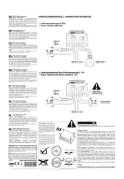
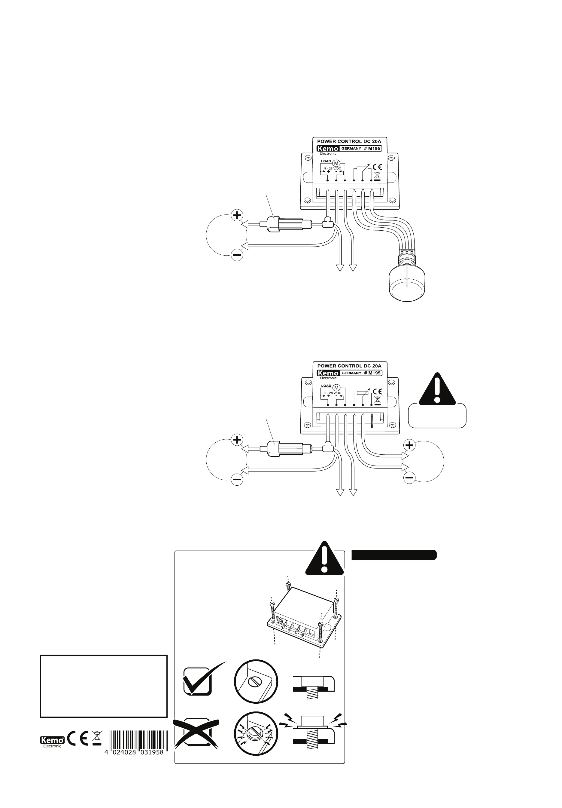
Das beiliegende Potentiometer wird gemäß Zeichnung über die
Steckkontakte mit dem Modul verbunden. Bitte darauf achten, dass die
Kabel nicht vertauscht werden!
Die Betriebsspannung (z.B. vom Akku) und die Last (z.B.
Gleichstrommotor) muss gemäß Zeichnung angeschlossen werden. Es
ist wichtig, dass Sie die Kabel möglichst kurz halten und auch Kabel mit
ausreichendem Querschnitt (2,5 - 4 mm²) verwenden. Wenn das Kabel
zu nn oder zu lang ist, dann haben Sie Leistungsverluste im Kabel
und der angeschlossene Motor läuft langsamer. Außerdem besteht
die Gefahr, dass zu dünne Kabel heiß werden, weil sehr hohe Ströme
ießen.
Bitte unbedingt eine Sicherung 20 A gemäß Anschlussplan vorschalten!!
Wichtig:
Die Belastbarkeit des Moduls ist max. 20 A! Bitte achten Sie unbedingt
darauf, dass Ihre angeschlossenen Lasten keine höhere Stromaufnahme
Hinweis: Bevor das Modul oder das Gerät in Betrieb
genommen oder zum ersten Mal installiert wird, muss
die ordnungsgemäße Funktion des Moduls oder des
Geräts von der Person überprüft werden, die das Teil
installiert oder in Betrieb nimmt.
Note: Before putting the module or device into opera-
tion, or installing it for the rst time, the proper functi-
on of the module or the device must be checked by a
person who installs the part or puts it into operation.
*Schrauben nicht enthalten | screws not included
DE | Wichtig! Die Alu-Grundplatte darf
keinen mechanischen Spannungen aus-
gesetzt werden (keine Löcher bohren,
nicht auf unebene Kühläche schrauben
usw.). Auf der Innenseite der Alu-Grund-
platte sind direkt anliegend empndliche
elektronische Bauteile montiert, die bei
mechanischen Bewegungen defekt wer-
den und das Modul dann nicht mehr
arbeitet!
EN | Important! The aluminium base
plate must not be exposed to mecha-
nical tension (do not drill holes, do not
screw on an uneven cooling surface,
etc.). Sensitive electronic components
are mounted directly adjacent on the in-
side of the aluminium base plate, which
become defective in case of mechanical
movements and the module then won’t
work any longer!
4x
9 - 28
V/DC
• Sicherung
• Fuse
20 A
ANSCHLUSSBEISPIELE | CONNECTION EXAMPLES
• Leistungsregelung mit Poti
• Power control with Poti
• Last (Motor, Lampe...)
• Load (motor, lamp...)
• Poti (beiliegend)
• Poti (included)
9 - 28
V/DC
• Sicherung
• Fuse
20 A
• Last (Motor, Lampe...)
• Load (motor, lamp...)
• Steuerspannung
• Control voltage
• Leistungsregelung über Gleichspannung 0 - 5 V
• Power control over direct current 0 - 5 V
• ohne Poti!
• without Poti!
0 - 5
V/DC
haben! Es gibt Motoren, die im Laufbetrieb eine Stromaufnahme
von z.B. 8 A haben, im Anlauf (beim Starten) oder im blockiertem
Zustand aber >30 A brauchen! Diese zerstören den Regler.
Inbetriebnahme:
Nach dem Einschalten der Betriebsspannung können Sie mit
dem Potentiometer die gewünschte Leistung einstellen (regeln).
Wichtige Montagehinweise, bitte beachten!
Je nach Belastung kann sich das Modul mehr oder weniger
erwärmen. Die Wärme entsteht an der Alu-Platte am Boden des
Moduls und muss gemäß Einbauanleitung unter bestimmten
Umständen durch die Montage auf eine hläche gekühlt
werden.
Dabei ist es wichtig, dass das Modul mit 4 Schrauben M3
oder Blechschrauben 2,9 mm plan auf ein kühlendes, planes
Kühlblech montiert wird. Das kann auch die Rückwand eines
Metallgehäuses sein. Wichtig ist, dass sich die Alu-Unterseite
des Moduls dabei nicht verzieht! Sie dürfen also keine größeren
Schrauben nehmen und die Löcher am Modul aufbohren. Die
Schraubenköpfe müssen auf dem Blech des Moduls auiegen
und nicht auf dem Plastikrand des Moduls! Bei der Montage
darf sich das Modul auch nicht verziehen (wenn der Untergrund
nicht plan ist). Der Grund: Auf der Innenseite des Alu-Bodens
des Moduls sind über einer nnen Isolierschicht direkt die
elektronischen SMD-Bauelemente aufgelötet und wenn sich
der Alu-Boden des Moduls verzieht, lösen sich die Lötstellen
und das Modul geht defekt. Bitte achten Sie auch darauf, dass
die in der Beschreibung als maximal angegebene Temperatur
der Bodenplatte nicht überschritten wird! Ansonsten muss eine
größere Kühlplatte angeschraubt werden!
Checkliste zur Fehlersuche:
Die angeschlossene Last lässt sich nicht auf volle Leistung
(100%) regeln:
1. Hat die Stromquelle eine ausreichende Leistung? Sie können
keinen Motor mit einer Leistungsaufnahme von z.B. 100 W an
einem kleinen 12 V Motorradakku betreiben! Bitte messen Sie
im Betrieb nach, ob die Eingangsspannung am Modul so hoch
ist, wie sie sein muss für die Last!
2. Die Kabel können zu dünn oder zu lang sein!
Wenn Sie den Regler auf volle Leistung gestellt haben, sind die
Kabelverluste bei zu nnem Kabel am Höchsten. Verwenden
Sie dickere Kabel (ideal 4 mm²).
Der Regler regelt nicht wie gewünscht: Linksdrehung langsam,
Rechtsdrehung schnell:
In diesem Fall vertauschen Sie bitte die beiden äußeren
Potikabel am Modul (umstecken). Das mittlere Kabel, dass
zum mittleren Potianschluss führt, muss so bleiben.
Trotz richtigem Anschluss ist an der Last ständig die volle
Leistung, lässt sich mit dem Regler nicht runterregeln:
Das Modul wurde durch einen Kurzschluss, Überlastung (>20
A) oder Überhitzung (keine Kühlung) zerstört. Weil jedes Modul
vor der Auslieferung sorgfältig geprüft wurde, ist in so einem
Fall keine Gewährleistung möglich.
Technische Daten:
Betriebsspannung: 9 - 28 V/DC | Max. Strombelastbarkeit:
20 A (wenn das Modul auf eine hlplatte geschraubt wird)
| Regelbereich: ca. 0% bis 100% | Regelungsart: PWM
Impulsbreitensteuerung mit einer Frequenz zwischen 300
- 600 Hz 4,7 k lin (liegt bei) | Potentiometer: | Zulässige
Lasten: Gleichstrommotoren, Glühlampen, Heizungen, LEDs
mit Vorwiderständen. Jeweils bis max. 20 A Stromaufnahme |
Maße: ca. 87 x 60 x 33 mm (mit Befestigungsboden)
Entsorgung:
Wenn das Gerät entsorgt werden soll, darf es nicht in den
Hausmüll geworfen werden. Es muss an Sammelstellen für
Fernsehgeräte, Computer usw. entsorgt werden (bitte erkundigen
Sie sich in Ihrem Gemeindebüro oder in der Stadtverwaltung
nach Elektronik-Müll-Sammelstellen).
EN
Use as directed:
Power regulation of direct-current consumers such as motors,
lamps, etc.
Assembly instructions:
The module may heat depending on the load. Therefore, it has to
be mounted in a dry and well ventilated place. In case of loads
of more than 5 A (up to max. 20 A) the module with the metallic
base area has to be cooled. This is done by attaching it planely
on a heat sink or bigger metallic piece (e.g. angle section,
metallic plate) in such a manner that the metallic base plate of
the module will not heat to more than +70°C under highest load
(the connected load runs at max. power).
The operating voltage of the module must be between 9 - 28
V and come up to the operating voltage of the connected load.
Example: When operating a 12 V motor the operating voltage
must be 12 V.
The attached potentiometer has to be connected with the
module via the plug contacts according to the drawing. Please
make sure that the cables will not be exchanged!
The operating voltage (e.g. from the battery) and the load (e.g.
direct current motor) have to be connected according to the
drawing. It is important to keep the cables as short as possible
and also to employ cables with a sufcient cross-section (2.5 - 4
mm²). If the cable is too thin or too long power losses will occur
in the cable and the connected motor runs slower. Furthermore,
there is the risk that too thin cables will become hot because
very high currents ow.
It is absolutely necessary to connect a fuse 20 A in series
according to the connecting diagram!!
Important:
The capacity of the module is max. 20 A! Please make sure that
the connected loads do not have a higher current consumption!
There are motors, which have a current consumption of e.g. 8
A during operation but require >30 A during the start-up or in
blocked condition! These will destroy the controller.
Setting into operation:
The desired output may be adjusted (controlled) with the
potentiometer after switching on the operating voltage.
Important installation instructions, please note!
Depending on the load the module heats up. The heat is
dissipated from the aluminum plate at the bottom of the module.
Under certain circumstances it must be mounted on a cooling
surface according to installation instructions.
It is important that the module is xed with 4 M3 screws (or 2.9
mm metal screws) on the cooling surface. This may be the back
wall of a metal casing. The aluminum plate on the bottom of
the module must not bend, do not use larger screws and do not
drill larger holes. The screw heads must rest on the plate of the
module, rather than on the plastic edge of the module! During
assembly, the module should not be curled up (if the ground
is not at). The reason: on the inside of the aluminum base of
the module the thin insulating layer are directly soldered on the
electronic SMD components. When the aluminum oor of the
module curls up, the joints and the module start loosen and the
module is defective. Please ensure that the maximum specied
temperature (as specied in the module‘s description) is not
exceeded. Otherwise apply a larger cooling plate.
Check list for troubleshooting:
The connected load cannot be adjusted to maximum output
(100%):
1. Does the current source have sufcient power? It is not
possible to operate a motor with a power consumption of e.g.
100 W at a small 12 V motorbike battery! Please measure
during operation whether the input voltage at the module is as
high as it should be for the load!
2. The cables may be too thin or too long! If you have adjusted
the controller to maximum output, the cable losses are the
highest with too thin cables. Please use thicker cables (ideal
4 mm²)
The controller does not control as desired: slow left-hand
rotation, quick right-hand rotation:
In this case please exchange the two outer potentiometer
cables at the module (unplug and plug). The central cable that
leads to the connection of the potentiometer has to stay where
it is.
The load has continuously full power despite correct
connection and cannot be dimmed with the controller:
The module was destroyed through a short-circuit, overcharge
(>20 A) or overheating (no cooling). As every module has been
carefully tested before delivery, guarantee is not possible in
such a case.
Technical data:
Operating voltage: | Max. current carrying 9 - 28 V/DC
capacity: 20 A (if the module is screwed on a cooling plate)
| Control range: approx. 0% to 100% PWM | Control mode:
pulse width modulation with a frequency between 300 - 600
Hz | Potentiometer: | Permissible loads: 4.7 k lin (enclosed)
direct current motors, incandescent lamps, heatings, LEDs
with protective resistors. Current consumption up to max. 20
A in each case approx. 87 x 60 x 33 mm (with | Dimensions:
mounting bottom)
Disposal:
This device may not be disposed with the household waste. It has
to be disposed at collecting points for television sets, computers,
etc. (please ask your local authority or municipal authorities for
these collecting points for electronic waste).
CZ
Použití modulu:
Modul se používá k regulaci výkonu u jednosměrných spotřebičů
proudu, např. motorů, žárovek, atd.
Montáž:
Modul se v závislosti od zátěže může zahřívat. Proto jeho montáž
musí být realizována na suchém dobře provětrávaném místě.
Při zátěži více než 5 A (do max. 20 A) modul musí být chlazen
s pomocí metalického chladiče. To znamená, že se použije
plochý chladič, nebo větší kus kovového materiálu (např. kovo
prol, kovová deska), na který se modul přišroubuje, a to takých
rozměrů, při kterých teplota chladiče při max. zátěži (připojena
zátěž běží na plný výkon) nepřesáhne hodnotu +70°C.
Pracovní napětí modulu musí být mezi 9 - 28 V a musí zodpovídat
připojené zátěži. Příklad: Při použí 12 Voltového motoru,
pracovní napětí musí být taky 12 V.
Přiložený potenciometr je třeba připojit podle výkresu k modulu.
Dávejte přitom prosím pozor na to, aby ste nezaměnili kabely!
Pracovní napětí (např. z akumulátoru) a zátěž musí být připojeny
podle výkresu. Je důležité, aby byl kabel co nejkratší a aby jeho
průřez byl dostatečně velký (2,5 - 4 mm²). Když je kabel příl
tenký, nebo příliš dlouhý, vznikají v něm straty a připojený motor
běží pomaleji. Kromě toho je nebezpečí, že se přehřeje, prote
v něm tečou velmi vysoké proudy.
Naléhavě Vás žádame, aby ste podle vodu do obvodu
předřadili pojistku 20 A!!
Důležíté:
Maximálně dovolená zátěž modulu je 20 A. Dejte bezpodmíněč
pozor na to, aby ste nepřipojili zátěž s větším odberěm proudu!
Motory, které mají proudový odběr za chodu na úrovni např. 8
A, při zapnutí, nebo v stavu blokace maale odběr >30 A. Taká
situace je příčinou zničení modulu.
Uvedení do provozu:
Po připojení pracovního napětí můžete pomocí potenciometru
nastavit požadovaný výkon (regulovat).
Důležité pokyny k instalaci, respektujte prosím!
V závislosti na zatížení modulu více či méně tepla. Tepla je
izolován v hliníkovém modulu a Za určitých okolností musí
být v souladu s pokyny přes montáž na povrchu chladící vody
vypouštěné.
Je ležité, aby modul byl namontován na rovnou plochu
chlazení pomocí 4-ch šrouby M3 nebo 2.9 mm sebe-šrouby.
Může být použit pro tento účel zadní stěny kovového pouzdra. Co
je důležité je, aby nevyvolával ohybu hliníkové základní modul! Je
zakázáno otvory a použít větší šrouby. Hlavy šroubů muležet
na povrchu modulu hliníkového plechu, a ne na okraji plastu! Při
montáži modulu nelze ohýbat (v případě, že povrch, na kterém je
namontována, není plochá). vod: na vnitřní hliníkové základny,
tenkou izolačvrstvou, jsou přímo připájeny SMD elektronické
součástky, které se v případě ohýbání hliníkové základny a
vyjměte modul je poškozen. Vezměte prosím na vědomí, že
maximum uvedené v návodu, teplota hliníkové základny, nebyla
překročena! V opačném případě by měl být modul připevněn k
větší chladící deskou!
Řešení problémů:
Připojena zátěž se nedá regulovat na plný výkon (100%):
1. zdroj napájení dostatečný výkon? Žádmotor s výkonem
např. 100 W se nedá napájet od malé 12 V baterie. Změřte
dopředu, jestli vstupní napětí na modulu má takovou hodnotu,
jakou.
2. Kabel může být přitenký nebo přidlouhý. Když nastavíte
regulaci na plný výkon, straty v kabelu jsou v případě tenkého
kabelu nejvyšší. Použijte proto kabel s větším průřezem (ideálne
4 mm²).
Regulátor nepracuje tak, jak je požadované: Otáčky doleva
jsou pomalé, doprava jsou rychlé:
V tomto případě vyměňte místem obidva vnější přívody
potenciometru na modulu. Střední kabel zůstáva nezměnem.
Přes správne zapojení je na těži stále plný výkon, s
regulátorem se nedá regulovat:
Modul byl skratován, byl přetížen (>20 A), nebo byl přehřátý
(žádné chlazení) a je zničen. Protože kdý modul je před
dodávkou pečlivé skontrolován, není možnáhrada v rámci
záruky novým modulem.
Technické údaje:
Pracovní napětí: | Maximální zátěž: 9 - 28 V/DC 20 A (v případě,
když je modul pevspojen s chladičem) | Rozsah regulace:
cca od 0% do 100% PWM impulsní regulace | Metoda regulace:
s frekvenmezi 300 - 600 Hz | Potenciometr: 4,7 k lineární
(přiložen) Jednosměrné motory, žárovky, | Dovolená zátěž:
topení LED diody s předřadným odporem. Každá zátěž do max.
proudové spotřeby 20 A | Rozměry: cca. 87 x 60 x 33 mm (with
mounting bottom)
Likvidace:
Má-li být vysloužilý přístroj odstraněn, nesmí se házet do
domovního odpadu. Musíte jej odevzdat na stě sběru vysloužilé
elektroniky (sběrný dvůr apod).
ES
Uso previsto:
Regulación de potencia de consumidores de corriente continua
como motores, lámparas, etc.
Instrucciones de montaje:
El módulo se puede calentar según la carga. Por tanto se debe
montar en un sitio seco y bien ventilado. En caso de cargas
de más de 5 A (hasta 20 A como ximo) el módulo se debe
refrigerar con la placa de base metálica. Eso se efectua por
montarlo llanamente sobre un disipador de calor o una pieza
metálica más grande (p.ej. perl angular, placa metálica) de
manera que la placa de base metálica del módulo no se calente
a más de +70°C con carga máxima (la carga conectada marcha
a potencia máxima).
La tensión de servicio del módulo debe ser entre 9 - 28 V y debe
corresponder a la tensión de servicio de la carga conectada.
Ejemplo: al accionar un motor 12 V, la tensión de servicio debe
ser 12 V.
Conectar el potenciómetro adjuntado con el módulo vía los
contactos enchufables. ¡Prestar atención a no cambiar los
cables!
La tensión de servicio (p.ej. del acumulador) y de la carga (p.ej.
motor de corriente continua) se deben conectar según el dibujo.
Es importante de tener los cables lo más corto posible y de
emplear también cables con una sección transversal suciente
(2,5 - 4 mm²). Si el cable es demasiado delgado o demasiado
largo, se producen pérdidas de potencia en el cable y el motor
conectado marcha s despacio. Además hay el peligro que
cables demasiado delgados se calentan porque altas corrientes
uyen.
¡Es de necesidad absoluta de preconectar un fusible 20 A según
el diagrama de conexión!!
Importante:
iLa capacidad de carga del módulo es 20 A como máximo!
¡Prestar atención a lo que las cargas conectadas no tengan
un consumo de corriente más alto! ¡Hay motores que tienen
un consumo de corriente de p.ej. 8 A durante la marcha, pero
necesitan >30 A durante el arranque o en estado bloqueado!
Estos van a detruir el regulador.
Puesta en servicio:
Después de conectar la tensión de servicio Vd. puede ajustar
(regular) la potencia deseada mediante el potenciómetro.
¡Instrucciones de montaje importantes a tener en cuenta!
El módulo puede calentarse más o menos dependiente de la
carga. El calor se desarrolla a la placa de aluminio al fondo del
módulo y se debe refrigerar bajo ciertas circunstancias según las
instrucciones de instalación por el montaje sobre una supercie
de refrigeración.
En este contexto es importante de montar el módulo con 4
P / Module / M195 / Beschreibung / 10040DI / Karton 1 (M195) / Ver.002 2/4


Produkt Specifikationer

Mærke: Kemo
Kategori: Legetøj
Model: M195

Har du brug for hjælp?

Hvis du har brug for hjælp til Kemo M195 stil et spørgsmål nedenfor, og andre brugere vil svare dig