Designed to meet international safety standards.
IEC61010-1.IEC61010-031 & IEC61010-2-032
Measurement Category (CAT) IV 600V
Double molded main body provides comfortable
LCD Backlight function to facilitate working at dimly
REL function to indicate measurement variation
(Current, voltage, Resistance measurement)
MIN/MAX function enables easy reading of min &
max value during measurement.
PEAK Hold Function enables Peak value measure-
ment of starting current. (only at ACA Range)
With Continuity & Diode Check Function
Capacity measurement of capacitors
Temperature measurement, switchable between ℃
NCV (Non Contact Voltage) Function for wiring check
Sleep Function to extend battery life
With Bar Graph, 6039 count display
This instrument has been designed,manufactured and
tested according to IEC 61010: Safety requirements
for Electronic Measuring apparatus, and delivered in
the best condition after passed the inspection.
This instruction manual contains warnings and safety
rules which must be observed by the user to ensure
safe operation of the instrument and retain it in safe
Therefore, read through these operating instructions
before using the instrument.
Read through and understand the instructions
contain e d in this ma nual befo r e usi n g th e
Keep the manual at hand to enable quick reference
The instrument is to be used only in its intended
Understand and follow all the safety instructions
It is essential that the above instructions are
Failure to follow the instructions may cause injury,
instrument damage and/or damage to equipment
under test. Kyoritsu is by no means liable for any
damage resulting from the instrument in contradiction
The symbol indicated on the instrument means #
that the user must refer to the related parts in the
manual for safe operation of the instrument. It is
essential to read the instructions wherever the #
symbol appears in the manual.
# DANGER is reserved for conditions and actions
that are likely to cause serious or fatal injury.
# WARNING is reserved for conditions and actions
that can cause serious or fatal injury.
# CAUTION is reserved for conditions and actions
that can cause injury or instrument damage.
Marks listed in the table below are used on this
User must refer to the manual.
Instrument with double or reinforced insulation
Indicates that this instrument can clamp on
bare conductors when measuring a voltage
corresponding to the applicable measurement
category, which is marked next to this symbol.
Th is in st ru me nt sa ti sf ie s t he m ar k i n g
requirement defined in the WEEE Directive.
This symbol indicates separate collection for
electrical and electronic equipment.
Never make measurement on a circuit in which
voltage over AC600V exists.
Do not attempt to make measurement in the
presence of flammable gasses. Otherwise, the
use of the instrument may cause sparking, which
can lead to an explosion.
Transformer jaw tips are designed not to short the
circuit under test. If equipment under test has
expo s e d conductive parts, however, extra
precaution should be taken to minimize the
Never attempt to use the instrument if its surface
Do not exceed the maximum allowable input of
N e v e r o p e n t h e B a t t e r y c o v e r d u r i n g a
The instrument is to be used only in its intended
applications or conditions. Otherwise, safety
functions equipped with the instrument doesn't
work, and instrument damage or serious personal
Verify proper operation on a known source before
use or taking action as a result indication of the
Keep your fingers and hands behind the protective
fingerguard during measurement.
Never attempt to make measurement if any
abnormal conditions, such as broken case and
exposed metal parts are found on the instrument.
Do not rotate the Function Switch while the test
leads are being connected.
Do not install substitute parts or make any
modification to the instrument. For repair or re-
calibration, return the instrument to your local
distributor from where it was purchased.
Do not try to replace the batteries if the surface of
Disconnect all the cords and cables from the
object under test and power off the instrument
before opening the Battery Cover for Battery
Stop using the test lead if the outer jacket is
damaged and the inner metal or color jacket is
Set the Function Switch to an appropriate position
before starting measurement.
Firmly insert the test leads.
Disconnect the test leads from the instrument for
Do not expose the instrument to the direct sun,
high temperature and humidity or dewfall.
Altitude 2000m or less. Appropriate operating
temperature is within 0 and 40 .℃ ℃
This instrument isn't dust & water proofed. Keep
away from dust and water.
Be sure to power off the instrument after use.
When the instrument will not be in use for a long
period, place it in storage after removing the
Use a cloth dipped in water or neutral detergent
for cleaning the instrument. Do not use abrasives
To ensure safe operation of measuring instruments,
IEC 61010 establishes safety standards for various
electrical environments, categorized as O to CAT IV,
and called measurement categories. Higher-numbered
categories correspond to electrical environments with
greater momentary energy, so a measuring instrument
designed for CAT III environments can endure greater
momentary energy than one designed for CAT II.
O : Circuits which are not directly connected to
CAT II : Electrical circuits of equipment connected
to an AC electrical outlet by a power cord.
CAT III : Primary electrical circuits of the equipment
connected directly to the distribution panel,
and feeders from the distribution panel to
CAT IV : The circuit from the service drop to the
service entrance, and to the power meter
and primary over-current protection device
3-1. Measuring range & accuracy
(accuracy guaranteed at 23℃ ℃±5 , humidity
45~85%) AC Current 600A, 1000A Function
DC Current 600A, 1000A Function
600A 0-600.0A ±1.5%rdg±5dgt
(Auto-ranging, Input impedance: approx. 10M )Ω
(Auto-ranging, Input impedance: approx. 10M )Ω
Resistance (Diode Check/ Continuity/ Capacity)
0-600.0 Buzzer sounds at 100 or lessΩ Ω
the accuracy is not guaranteed
400 F the accuracy is not guaranteedμ
4000 F the accuracy is not guaranteedμ
Frequency/DUTY Function(Auto-ranging for Frequency)
(Pulse width/Pulse period)
Note: Mea su r ab l e inp u ts ar e : 40Vrm s@A CV or
50Arms@AC600A, 350A@AC1000A Range
Above specified accuracy is applied to Clamp meter
itself. Accuracy of Temperature probe is excluded.
When measuring temperature, include the accuracy of
the temperature probe used.
3-2. General Specification
Display : max. 6039 counts
(Frequency: 9999, Capacity &Temperature:4039)
Over-range indication : "OL" displayed when exceeding
(except for AC/DCV and 1000A Function)
Auto-ranging/Voltage, Resistance, Capacity Range
Single range / Continuity, Diode check, DUTY and
Sample rate : three times per second
OFF/ ACA/ ACV/ DCA/ DCV/ / / Ω℃ ℉
SELECT(AC/DC switching &/ / Ω
PEAK HOLD/ Back Light, REL
Power source : DC3V/ R03(UM-4) x 2pcs
Low battery warning : " " mark is displayed at
: 23 , relative humidity ℃ ℃±5
accuracy guaranteed 85% or less (no condensation)
0~40 , relative humidity 85%℃
& humidity range or less (no condensation)
Storage temperature : -20~60 , relative humidity ℃
Current consumption : approx. 25 mA
Sleep Function : Automatically powered off in about
15 min after the last Function switch operation.
Rotate the Function Switch from OFF to any
position to exit from the Sleep state.
Outdoor use, Altitude up to 2000m
IEC 61010-1, 61010-2-032, 61010-2-033
Measurement CAT IV 600V Pollution degree 2
・ EN 61000-4-2 (performance criterion B)
・ EN 61000-4-3 (performance criterion B)
Current Range : 720A AC/ 10 sec@KEW2046R
1200A AC/DC/ 10 sec@KEW2056R
Voltage Range : 720V AC/DC/ 10sec
Resistance Range : 600V AC/DC/ 10sec
6720V AC ( )TRMS 50/60Hz / 5 sec
(between Jaws and electrical circuit/ between
internal circuit and enclosure)
(between electrical circuit and enclosure)
approx. 254(L)×82(W)×36(D)mm / KEW2056R
approx. 243(L)×77(W)×36(D)mm / KEW2046R
Weight : approx 300g @ KEW2046R
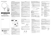
Test Leads M-7066A / 1 set
Battery R03 UM-4 / 2pcs( )
Instruction manual English, Japanese / 1pce
Carrying Case M-9094 / 1pcs
K-type Temperature Probe M-8216
Guaranteed accuracy range:
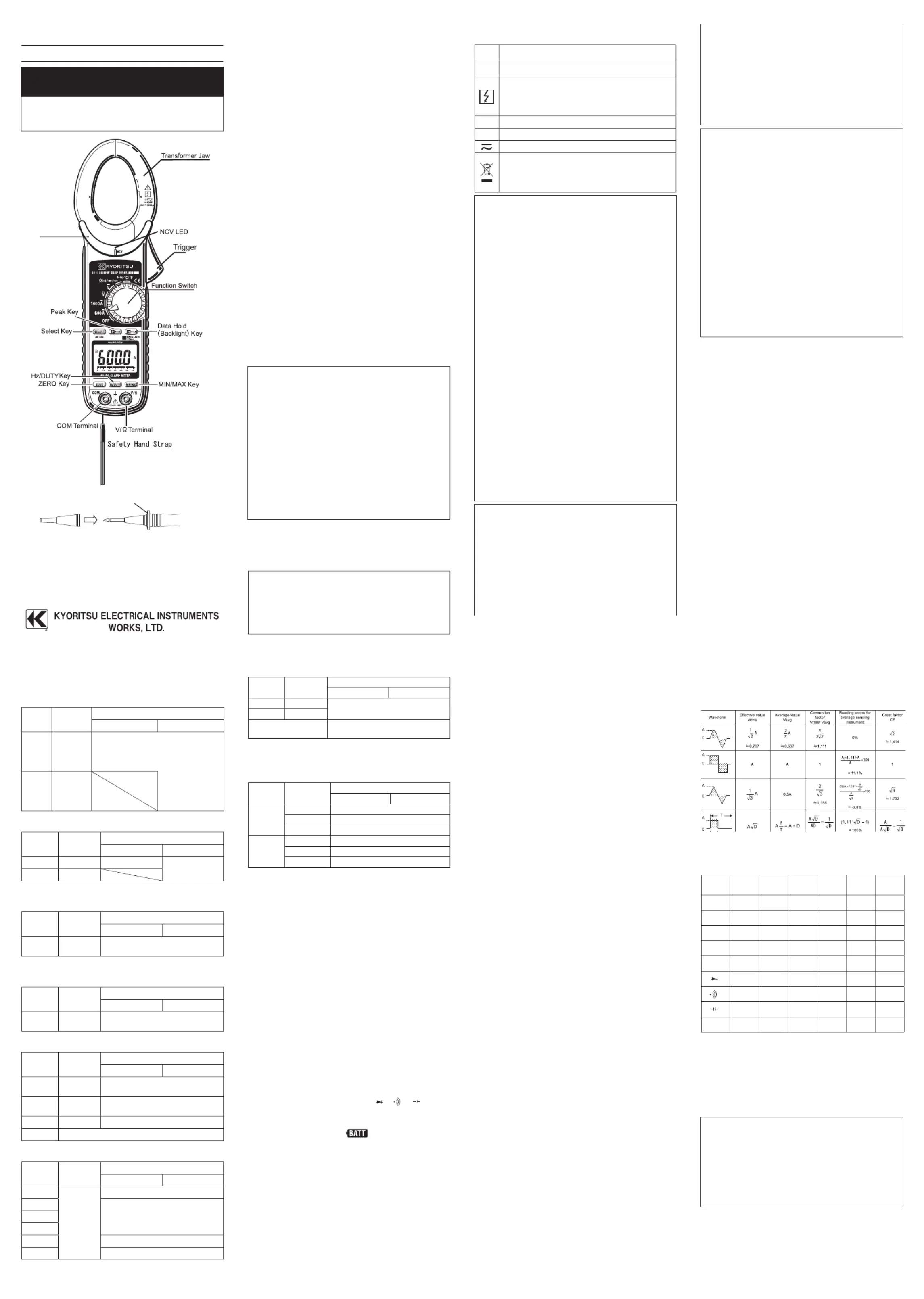
Most # alternating currents and voltages are
expressed in effective values, which are also
referred to as RMS (Root-Mean-Square) values.
The effective value is the square root of the
average of square of alternating current or voltage
values. Many clamp meters using a conventional
rec t ify i ng ci r cui t have " R MS" s c ale s for AC
measurement. The scales are, however, actually
calibrated in terms of the effective value of a sine
wave though the clamp meter is responding to the
average value. The calibration is done with a
conversion factor of 1.111 for sine wave, which is
found by dividing the effective value by the average
value. These instruments are therefore in error if the
input voltage or current has some other shape than
CF (Crest Factor) is found by dividing the peak
value by the effective value.
Examples: Sine wave: CF=1.414
Square wave with a 1: 9 duty ratio: CF=3
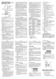
The "●" mark shows available function at each
4. Preparation for measurement
4-1. Checking Battery Voltage
Set the Function Switch to any position other than
"OFF". When the display is clear without "BATT" mark,
showing battery voltage is enough. When the display is
blank or "BATT" mark is indicated, replace the batteries
according to Section 7, Battery Replacement.
The Sleep f e a ture au tomatically powers the
instrument off in about 15 min after the last switch or
key operation. Therefore, the display may be blank
even with the Function Switch set to a position other
than "OFF". To operate the instrument in this case,
turn the switch back to the "OFF" position, then to
any other position. Replace the batteries if nothing
was displayed after above operations.
4-2. Checking Switch Setting & Operation
Confirm the Function Switch is set to the correct
po sition,the instrument is set to the co rrect
measurement mode,and the Data hold function is
disabled. Otherwise,desired measurement cannot be
Protective fingerguard (Barrier)
It is a part providing protection against electrical
shock and ensuring the minimum required air and
Uncapped condition for CAT II environment
Capped condition for CAT III/ IV environments
The Cap shuld be firmly attached to the probes.