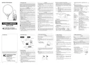
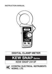
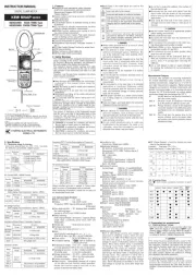
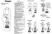
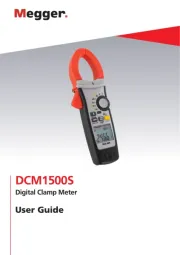
INSTRUCTION MANUAL
DIGITAL CLAMP METER
KEW 2055
1.Features
●
Designedtomeetinternationalsafetystandards.
IEC61010-1.IEC61010-031:2002&IEC61010-2-032
MeasurementCategory(CAT)IV600V
PollutionDegree2
●
Double molded main body provides comfortable
singlehandedgrip
●
DataHoldFunction
●
LCD Backlight function to facilitate working at
dimlylitsituations.
●
RELfunctiontoindicatemeasurementvariation.
(Current,voltage,Resistancemeasurement)
●
MIN/MAX function enables easy reading of min &
maxvalueduringmeasurement.
●
WithContinuity&DiodeCheckFunction
●
NCV
(
Non Contact Voltage
)
Function for wiring
check.
●
600Vinputprotection.
●
Sleepfunctiontoextendbatterylife.
●
WithBarGraph,6039counts
2. Safety Warnings
This instrument has been designed, manufactured and
testedaccordingtoIEC61010:Safetyrequirementsfor
Electronic Measuring apparatus, and delivered in
the best condition after passed the inspection. This
instruction manual contains warnings and safety
rules which must be observed by the user to ensure
safeoperation of the instrument and retain it in safe
condition.
Therefore, read through these operating instructions
beforeusingtheinstrument.
WARNING
●
Read through and understand the instructions
contained in this manual before using the
instrument.
●
Keep the manual at hand to enable quick
referencewhenevernecessary.
●
Theinstrumentistobeusedonlyinitsintended
applications.
●
U n d e r s t a n d a n d f o l l o w a l l t h e s a f e t y
instructionscontainedinthemanual.
Failure tofollow the instructions may cause injury,
instrument damage and/or damage to equipment
under test. Kyoritsu is by no means liable for
any damage resulting from the instrument in
contradictiontothiscautionarynote.
Thesymbol indicatedontheinstrumentmeansthat
theusermustrefertotherelatedpartsinthemanual
forsafe operation ofthe instrument. It isessential to
read the instructions wherever the symbol appears
inthemanual.
DANGER is reserved for conditions and actions
that are likely to cause serious or fatal injury.
WARNING is reserved for conditions and actions
that can cause serious or fatal injury.
CAUTION is reserved for conditions and actions
that can cause injury or instrument damage.
●
Marks listed in the table below are used on this
instrument.
Usermustrefertothemanual.
Instrumentwithdoubleorreinforcedinsulation
Indicates that this instrument can clamp on
bare conductors when measuring a voltage
corresponding to the applicable measurement
category,whichismarkednexttothissymbol.
AC
DC
AC&DC
Thisinstrumentsatisfiesthemarkingrequirement
defined in the WEEE Directive (2002/96/EC).
This symbol indicates separate collection for
electricalandelectronicequipment.
DANGER
●
Never make measurement on a circuit in which
voltageoverAC600Vexists.
●
Do not attempt to make measurement in the
presenceof flammable gasses. Otherwise, the use
of the instrument may cause sparking, which can
leadtoanexplosion.
●
Transformer jaw tips are designed not to short
the circuit under test. If equipment under test
has exposed conductive parts, however, extra
precaution should be taken to minimize the
possibilityofshorting.
●
Neverattempttousetheinstrumentifitssurface
oryourhandiswet.
●
Do not exceed the maximum allowable input of
anymeasuringrange.
●
N e v e r o p e n t h e B a t t e r y c o v e r d u r i n g a
measurement.
●
The instrument is to be used only in its intended
applications or conditions. Otherwise, safety
functionsequippedwiththeinstrumentdoesn
twork,
and instrument damage or serious personal injury
maybecaused.
●
Verify proper operation ona known source before
use or taking action as a result indication of the
instrument.
●
Keepyourfingersandhandsbehindtheprotective
fingerguardduringmeasurement.
WARNING
●
Never attempt to make measurement if any
abnormal conditions, such as broken case and
exposedmetalpartsarefoundontheinstrument.
●
Do not rotate the Function Switch while the test
leadsarebeingconnected.
●
Do not install substitute parts or make any
modification to the instrument. For repair or
re-calibration, return the instrument to your local
distributorfromwhereitwaspurchased.
●
Donot try to replace the batteries if the surface
oftheinstrumentiswet.
●
Disconnect all the cords and cables from the
object under test and power off the instrument
before opening the Battery Cover for Battery
replacement.
●
Verify proper operation ona known source before
useortakingactionasaresultoftheindicationof
theinstrument.
●
Use appropriate personal protective equipment
such as insulating gloves, Insulating boots, and
safetyglasses.
●
Stop using the test lead if the outer jacket is
damaged and the inner metal or color jacket is
exposed.
CAUTION
●
SettheFunctionSwitchtoanappropriateposition
beforestartingmeasurement.
●
Firmlyinsertthetestleads.
●
Disconnectthetestleadsfromtheinstrumentfor
currentmeasurement.
●
Do not expose the instrument to the direct sun,
hightemperatureandhumidityordewfall.
●
Altitude 2000m or less. Appropriate operating
temperatureiswithin0
℃
and40
℃
.
●
This instrument isn
t dust & water proofed. Keep
awayfromdustandwater.
●
Be sure to power off the instrument after use.
Whentheinstrumentwill notbein usefora long
period, place it in storage after removing the
batteries.
●
Use a cloth dipped in water or neutraldetergent
for cleaning the instrument. Do not use abrasives
orsolvents.
Measurement Category
To ensure safe operation of measuring instruments,
IEC 61010 establishes safety standards for various
electrical environments, categorized as O to CAT IV,
and called measurement categories. Higher-numbered
categories correspond to electrical environments with
greatermomentary energy,so a measuringinstrument
designedforCATIII environmentscanendure greater
momentaryenergythanonedesignedforCATII.
O
:Circuits which are not directly connected
tothemainspowersupply.
CAT II
:Electrical circuits of equipment connected
toanACelectricaloutletbyapowercord.
CAT III
:Primary electrical circuits of the
equipment connected directly to the
distribution panel, and feeders from the
distributionpaneltooutlets.
CAT IV
:The circuit from the service drop to the
service entrance, and to the power meter
andprimaryover-currentprotectiondevice
(distributionpanel).
3. Specification
3-1. Measuring range & accuracy
(accuracyguaranteedat23
℃ ±
5
℃
.humidity45
〜
85%)
ACCurrent600A,1000AFunction
Function Measuring
Range Accuracy
600A 0-600.0A
±
1.5%rdg
±
5dgt
(50/60Hz)
±
3.5%rdg
±
8dgt
(40-400Hz)
1000A 0-1000A
DCCurrent600A,1000AFunction
Function Measuring
Range Accuracy
600A
0-600.0A
±
1.5%rdg
±
5dgt
1000A
0-1000A
ACVoltageFunction
(
Auto-ranging,Inputimpedance:approx.10M
Ω)
Range Measuring
Range Accuracy
6/60/600V 1-600.0V
±
1.3%rdg
±
4dgt(50/60Hz)
±
3.0%rdg
±
5dgt(40
〜
400Hz)
DCVoltageFunction
(
Auto-ranging,Inputimpedance:approx.10M
Ω)
Range Measuring
Range Accuracy
600mV/6/
60/600V 0-600.0V
±
1.0%rdg
±
3dgt
Resistance
(
Continuity/DiodeCheck
)
Function
Range Measuring
Range Accuracy
600
Ω
/6k/
60k/600k
Ω
6M
Ω
0-6M
Ω ±
1.0%rdg
±
5dgt
60M
Ω
6.00M-
60.00M
Ω±
5%rdg
±
8dgt
ContBuzzer 0-600.0
Ω
Thresholdvalue:60
Ω±
30
Ω
Diode Testvoltage:0-2V
Frequency/ DUTY Function
(
Auto-ranging for
Frequency
)
Range Measuring
Range Accuracy
ACA 40Hz
−
400Hz
±
0.5%rdg
±
5dgt
ACV 1Hz
〜
10kHz
0.1-99.9%
(Pulsewidth/Pulseperiod)
±
2.5%rdg
±
5dgt
Note:Measurableinputsare:40Vrms@ACVor
60Arms@AC600A,350A@AC1000ARange
3-2. General Specification
●
Modeofoperation
:
Δ
∑mode
●
Display
:max.6039counts
(Frequency:9999)&Bargraph
●
Over-range indication : "OL" displayed when exceeding
the measuring range. (except for AC/DCV and 1000A
Function)
●
Rangeswitching :
Auto-ranging/Voltage,ResistanceRange
Singlerange/Continuity,Diodecheckand
DUTY
●
Samplerate
:threetimespersecond
●
Functionalconstruction:
OFF/ACA/DCA/ACV/DCV/
Ω
●
Keys :
SELECT(AC/DCswitching&/
Ω
/ / ),REL
Δ
,
Hz/DUTY,MIN/MAX,HOLD/BackLight
●
Powersource :DC3V/R03(UM-4)x2pcs
●
Lowbatterywarning
:
" "markisdisplayedat
2.4V
±
0.15Vorless.
●
Temperature & humidity : 23
℃ ±
5
℃
, relative humidity
accuracyguaranteed85%orless(nocondensation)
●
Operatingtemperature:0
〜
40
℃
,relativehumidity
&humidityrange85%orless(nocondensation)
●
Storagetemperature :-20
〜
60
℃
,relativehumidity
&humidityrange85%orless(nocondensation)
●
Currentconsumption:approx.12mA
●
SleepFunction:Automaticallypoweredoffinabout
15minafterthelastFunctionswitchoperation.
Press any key or rotate the Function Switch from
OFFtoanypositiontoexitfromtheSleepstate.
●
Locationforuse
Outdooruse,Altitudeupto2000m
●
ApplicableStandards
IEC61010-1,61010-2-032,61010-2-033
MeasurementCATIV600VPollutiondegree2
IEC61010-031
EMC
:
EN61326-1
・
EN55022
・
EN61000-4-2(performancecriterionB)
・
EN61000-4-3(performancecriterionB)
●
RoHS
:
EN50581
●
OverloadProtection
CurrentRange :1200AAC/DC/10sec
VoltageRange :720VAC/DC/10sec
ResistanceRange :600VAC/DC/10sec
●
WithstandVoltage
6720VAC
(
TRMS50/60Hz
)
/5sec
(betweenJawsandelectricalcircuit/betweeninternal
circuitandenclosure)
●
InsulationResistance:10M
Ω
ormore/1000V
(
betweenelectricalcircuitandenclosure
)
●
Conductorsize
approx.40mm
●
Dimension
approx.254(L)
×
82(W)
×
36(D)mm
●
Weight:approx.:310g
●
Accessories
TestLeads Model7066A/1set
BatteryR03
(
UM-4
)
/2pcs
InstructionmanualEnglish,Japanese/1pce
CarriyngCaseModel9094/1pcs
3-3. Function Keys
The"
●
"markshowsavailablefunctionateachRange.
DCCurrentMeasurement
HOLD SELECT ZERO Hz/
DUTY MAX/
MIN
ACA
●●●●●
ACV
●
-
●●●
DCA
●●●
-
●
DCV
●
-
●
-
●
Ω●●●
-
●
-
●
---
-
●
---
4. Preparation for measurement
4-1. Checking Battery Voltage
Set the Function Switch to any position other than
"
OFF
".When thedisplayis clearwithout "
BATT
" mark,
showing, battery voltage is enough. When the display
is blank or
"
BATT
" mark is indicated, replace the
batteriesaccordingtoSection7,BatteryReplacement.
CAUTION
The Sleep feature automatically powers the
instrumentoffinabout 15minafterthe lastswitch
or key operation. Therefore, the display may be
blankevenwiththeFunctionSwitchsettoaposition
other than "
OFF
". To operate the instrument in this
case, turn the switch back to the "
OFF
" position,
thentoanyotherposition,orpressanykey.Replace
the batteries if nothing was displayed after above
operations.
4-2. Checking Switch Setting & Operation
Confirm the Function Switch is set to the correct
position, the instrument is set to the correct
measurementmode,
and the Data hold function is disabled. Otherwise,
desiredmeasurementcannotbemade.
5. Measurement
5-1. AC Current Measurement
DANGER
●
Never make measurement on a circuit in which
voltage over AC600V exists to avoid getting
electricalshock.
●
Transformer jaw tips are designed not to short
the circuit under test. If equipment under test has
exposedconductiveparts,however,extraprecaution
should be taken to minimize the possibility of
shorting.
●
Do not make measurement with the Battery Cover
removed.
●
Disconnect the test leads from the instrument for
currentmeasurement.
●
Keep yourfingersand handsbehindthe barrieron
theinstrumentduringameasurement.
(1)Set the Function Switch to "
600A
" or "
1000A
"
position.
AChasbeenselectedbydefault;presstheSELECT
key, when DC has been selected, to change it to
AC.AC mark isdisplayed at theupper left onthe
display.
(2)Pressthetriggertoopenthetransformerjawsand
clampthemontotheoneconductorundertest,then
take the reading on the display. Pressing the "
Hz/
DUTY
" Key switches the indication in following
sequence.
AC Current
⇨
Hz
⇨
DUTY
Hz/DUTY
Function requires 60A or more at AC600A
Rangeand350AormoreatAC1000Arange.
CAUTION
●
Max conductor size for KEW2055 is approx
dia. 40mm. During current measurement, keep
the trans former jaws fully closed. Other wise,
accuratemeasurementscannotbetaken.
5-2. DC Current Measurement
DANGER
●
Never make measurement on a circuit in which
voltage over DC600V exists to avoid getting
electricalshock.
●
DonotmakemeasurementwiththeBatteryCover
removed.
●
Keepyourfingersandhandsbehindthebarrieron
theinstrumentduringameasurement.
(1)Set the Function Switch to "
600A
" or "
1000A
"
position. AC has been selected by default; press
the SELECT key, when AC has been selected, to
changeittoDC.
DC mark is displayed at the upper left on the
display.
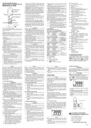
Barrier
O: Device which is
not directly
connected to the
mains power supply
Protectivefingerguard(Barrier)
:
It is a part providing protection against electrical
shock and ensuring the minimum required air and
creepagedistances.
Cap
:
UncappedconditionforCATIIenvironment
CappedconditionforCATIII/IVenvironments
TheCapshuldbefirmlyattachedtotheprobes.
Whenthe instrument and the testlead are combined
andusedtogether,whicheverlowercategoryeitherof
thembelongstowillbeapplied.
Cap
Protective fingerguard