INSTRUCTIONMANUAL
KEW MATE 2000A/2001A
DIGITAL MULTIMETER
WITH
AC/DC CLAMP SENSOR
KYORITSU ELECTRICAL INSTRUMENTS
WORKS, LTD.
1.SAFETY WARNINGS
ThisinstrumenthasbeendesignedandtestedaccordingtoIECPublication61010:
Safety Requirementsfor ElectronicMeasuring Apparatus. This instructionmanual
containswarnings andsafety rules whichmust beobserved bythe userto ensure
safeoperation ofthe instrumentand toretain itinsafe condition. Therefore,read
throughtheseoperatinginstructionsbeforestartingusingtheinstrument.
WARNING
●
Read through and understand instructions contained in this manual before
startingusingtheinstrument.
●
Saveandkeepthemanualhandytoenablequickreferencewhenevernecessary.
●
Be sure to use the instrument only in its intended applications and to follow
measurementproceduresdescribedinthemanual.
●
Besuretounderstandandfollowallsafetyinstructionscontainedinthemanual.
Theinstrumentistobeusedonlyinitsintendedapplications.
Understandandfollowallthesafetyinstructionscontainedinthemanual.
Failure to follow the instructions may cause injury, instrument damage and/or
damage to equipment under test. Kyoritsu is by no means liable for any damage
resultingfromtheinstrumentincontradictiontothiscautionarynote.
Failure to follow the above instructions may cause injury, damage to the instrument
and/ordamagetoequipmentundertest.
The symbol indicated on the instrument means that the usermust refer to related
partsofthemanualforsafeoperationof theinstrument.Besureto carefullyreadthe
instructionsfollowingeach symbolinthismanual.
DANGER
isreservedforconditionsandactionsthatarelikelytocauseseriousorfatalinjury.
WARNING
isreservedforconditionsandactionsthatcancauseseriousorfatalinjury.
CAUTION
isreservedforconditionsandactionsthatcancauseminorinjuryorinstrumentdamage.
Following symbols are used on the instrument and in the instruction manual. Attention
shouldbepaidtoeachsymboltoensureyoursafety.
Refertotheinstructionsinthemanual.
Thissymbolismarkedwheretheusermustrefertotheinstructionmanualsoasnot
tocausepersonalinjuryorinstrumentdamage.
Indicatesaninstrumentwithdoubleorreinforcedinsulation.
Indicatesthatthisinstrumentcanclamponbareconductorswhenmeasuring
avoltagecorresponding to theapplicableMeasurementcategory,which ismarked
nexttothissymbol
.
IndicatesAC(AlternatingCurrent)
.
IndicatesDC(DirectCurrent).
IndicatesACandDC.
DANGER
●
Never make measurement on circuits with a maximum voltage difference of
600VAC/DC or greater between conductors (300VAC/DC or greater between a
conductorandground).
●
Do not attempt to make measurement in the presence of flammable gasses.
Otherwise, the use of the instrument may cause sparking, which leads to an
explosion.
●
Neverattempttousetheinstrumentifitssurfaceoryourhandiswet.
●
Donotexceedthemaximumallowableinputofmeasuringranges.
●
Neveropenthebatterycompartmentcoverwhilemakingmeasurement.
●
Never try to make measurement if any abnormal conditions, such as broken
Transformerjawsorcaseisnoted.
●
The instrument is to be used only in its intended applications or conditions.
Otherwise, safety functions equipped with the instrument doesn
t work, and
instrumentdamageorseriouspersonalinjurymaybecaused.
WARNING
●
Never attempt to make any measurement, if any abnormal conditions are noted,
suchasbrokencase,crackedtestleadsandexposedmetalparts.
●
DonotturntheFunctionSelectorSwitch whilethetestleadsareconnectedto the
circuitundertest.
●
Do notinstall substitute parts ormake any modificationto the instrument. Return
theinstrumenttoKyoritsuoryourdistributorforrepairorre-calibration.
●
Donottrytoreplacethebatteriesifthesurfaceoftheinstrumentiswet.
●
Always disconnectthe clampsensor andthe testleads from thecircuit undertest
and switch off the instrument before opening the battery compartment cover for
batteryreplacement.
●
Stopusingthetestleadiftheouterjacket isdamagedandtheinnermetalorcolor
jacketisexposed.
CAUTION
●
MakesurethattheFunctionSelectorSwitchissettoanappropriatepositionbefore
makingmeasurement.
●
Always make sure to place the test leads in the test lead holder before making
currentmeasurement.
●
Donotexposetheinstrumenttothedirectsun,extremetemperaturesordewfall.
●
Besure toset theFunctionSelector Switchtothe "OFF"position afteruse.When
the instrument will not be usedfor a long period of time, place it in storage after
removingthebatteries.
●
Useadampcloth anddetergentforcleaning theinstrument.Do notuseabrasives
orsolvents.
●
Keepyourfingersandhandsbehindtheprotectivefingerguardduringmeasurement.
Measurement Category:
To ensure safe operation of measuring instruments, IEC 61010 establishes safety
standardsforvariouselectricalenvironments,categorizedasOtoCATIV,andcalled
measurement categories. Higher-numbered categories correspond to electrical
environments with greater momentary energy, so a measuring instrument designed
for CAT III environments can endure greater momentary energy than one designed
forCATII.
O :Circuitswhicharenotdirectlyconnectedtothemainspowersupply.
CATII :Electricalcircuits ofequipmentconnected toanACelectrical outlet bya
powercord.
CATIII :Primary electrical circuits of the equipment connected directly to the
distributionpanel,andfeedersfromthedistributionpaneltooutlets.
CATIV :Thecircuitfromtheservicedroptotheserviceentrance,andtothepower
meterandprimaryover-currentprotectiondevice(distributionpanel).
2.FEATURES
●
Permits AC/DC current measurement up to 60A using a clamp sensor that comes
standardwiththeinstrument
●
Clampsensorforeaseofuseincrowdedcableareasandothertightplaces
●
Permitscurrentmeasurementwithanopencurrent-clampsensorthatdoesnotrequire
openingandclosingoperationsbytheuser
●
Auto-power-savefunction
●
Buzzerforeasycontinuitychecking
●
Dataholdfunctiontofreezethereadings
●
LCDwitha3400countfullscalebargraph
●
Shockabsorbingholsterforeaseofstorage
●
Designed to international safety standard IEC61010-1: measurement category
CAT
Ⅲ
,300Vandpollutiondegree2.
O: Device which is
not directly
connected to the
mains power supply
3.SPECIFICATIONS
●
MeasuringRangesandAccuracy(at23
℃±
5
℃
,relativehumidity75%orless)
※
Electromagnetic
RFfield
≦
1V/m
compatibility
ACV/DCV/OHMS/FREQUENCYtotalaccuracy=specifiedaccuracy
(IEC61000-4-3)
ACA/DCA
totalaccuracy=specifiedaccuracy+5dgt
RF transmitters such as mobile telephones may not be used in close
proximity.
●
SafetyStandard IEC61010-1
measurementCAT
Ⅲ
,300V,pollutiondegree2
measurementCAT
Ⅱ
,600V,pollutiondegree2
IEC61010-031
IEC61010-2-032,IEC61010-2-033
IEC61326-1(EMC),EN50581(RoHS)
●
OperatingSystem Dualintegration
●
Display Liquid crystal display with maximum reading of 3399 as
wellasunitsandannunciators
Bargraphwithmaximumpointsof33
●
OverInputIndication "OL"ontheLCD(
Ω
rangesonly)
●
Auto-rangingOperation Shifts tothe nexthigher range whenbar graphincreases
to33points
Shifts tothe next lowerrange when bargraph decreases
to3points
●
SampleRateNumericreading:about400ms,
bargraph:about20ms
MODEL
2000A
2001A
Range
60A
100A
ACCurrent
A
DCCurrent
A
ACVoltage
V
Inputimpedance:10M
Ω
DCVoltage
VInputimpedance:10M
Ω
MeasuringRange
0-60.0A
0-100.0A
Accuracy
±
2.0%rdg
±
5dgt(50/60Hz)
±
2.0%rdg
±
5dgt(50/60Hz)
MODEL
2000A
2001A
Range
60A
100A
MeasuringRange
0-
±
60.0A
0-
±
100.0A
Accuracy
±
2.0
%
rdg
±
5dgt
±
2.0
%
rdg
±
5dgt
Range
3.4V
34V
340V
600V
MeasuringRange
0-600V
(Auto-ranging)
Accuracy
±
1.5%rdg
±
5dgt(50-400Hz)
Range
340mV
3.4V
34V
340V
600V
MeasuringRange
0-
±
600V
(Auto-ranging)
Accuracy
±
1.5%rdg
±
4dgt
Resistance
Ω/
Range
340
Ω
3.4k
Ω
34k
Ω
340k
Ω
3.4M
Ω
34M
Ω
MeasuringRange
0-33.99M
Ω
(Auto-ranging)
Accuracy
±
1.0%rdg
±
3dgt
Buzzerbeepsbelow30
±
10
Ω
(
Continuitybuzzerworkson340
Ω
range
only
)
±
5%rdg
±
5dgt
±
15%rdg
±
5dgt
Frequency
Hz
Range
Current
Voltage
MeasuringRange
0-3.399kHz
3.4kHz-10kHz
(Auto-ranging)
0-3.399kHz
3.4kHz-33.99kHz
34kHz-300kHz
(Auto-ranging)
Accuracy
±
0.1%rdg
±
1dgt
±
0.1%rdg
±
1dgt
●
Locationforuse Indooruse,Altitudeupto2000m
●
Accuracy-insured 23
℃±
5
℃
,relativehumidity75%orless
Temperatureand (withoutcondensation)
HumidityRanges
●
OperatingTemperature 0-40
℃
,relativehumidity85%orless
andHumidityRange (withoutcondensation)
●
StorageTemperature -20-60
℃
,relativehumidity85%orless
andHumidityRange (withoutcondensation)
●
Source Two1.5VDCR03(UM-4)batteries
●
CurrentConsumption Approx.10mA
●
Power-saveFunction Shifts tothepower-save stateabout 10minutesafter the
lastswitchoperation
(currentconsumption:approx.10
μ
A)
●
OverloadProtection AC/DCcurrentranges:MODEL2000A AC/DC 72A for
10seconds
AC/DCcurrentranges:MODEL2001A AC/DC
120
A for
10seconds
AC/DCvoltageranges:AC/DC720Vfor10seconds
Resistanceranges:AC/DC720Vfor10seconds
Frequencyranges:AC/DC720Vfor10seconds
●
WithstandVoltage AC3470V for 5 sec. between electrical circuit and
housingcase
●
InsulationResistance 10M
Ω
orgreaterat1000Vbetweenelectricalcircuitand
housingcase
●
ConductorSize MODEL2000AApprox.
6mmdiametermax.
MODEL2001AApprox.10mmdiametermax.
●
Dimensions MODEL2000A128(L)
×
87(W)
×
24(D)mm
MODEL2001A128(L)
×
92(W)
×
27(D)mm
●
Weight MODEL2000AApprox.210g
MODEL2001AApprox.220g
●
Accessories TwoR03(UM-4)batteries
InstructionManual
4.INSTRUMENT LAYOUT
Data Hold Button
MODEL2001 MODEL2000
Range Hold Button
Digital Multimeter
Function Selector Switch
Holster
Test Lead
LCD Display
AC/DC Clamp Sensor
Barrier Protective fingerguard
DCA
Zero Adjust
Knob
5.PREPARATIONS FOR MEASUREMENT
(
1
)
Checkingbatteryvoltage
SettheFunctionSelectorSwitchtoanypositionotherthantheOFFposition.
Ifthemarksonthe displayisclearlylegiblewithout symbol
"BATT"
showing,battery
voltage is OK. If the display blanks or
"BATT"
is indicated, replace the batteries
accordingtosection
8: Battery Replacement
.
NOTE
Whentheinstrumentisleftpoweredon,theauto-power-savefunctionautomatically
shutthepoweroff;ThedisplayblankseveniftheFunctionSelectorSwitchissetto
a position otherthan the OFF position in thisstate. To power on theinstrument,
turntheFunctionSelectorSwitchorpresstheDataHoldButton.Ifthedisplaystill
blanks,thebatteriesareexhausted.Replacethebatteries.
(
2
)
MakesurethattheFunctionSelectorSwitchissettotheappropriaterange.
Also make sure that data hold function is not enabled. If inappropriate range is
selected,desiredmeasurementcannotbemade.
(
3
)
InstallTestLeadtotheHolsteronthesideofbody
Itis possibleto measurewithseeing theLCD Displaykeep
TestLeadinstallingtotheHolster.
AC/DC
Auto Range
Data Hold
Unit
Bar Graph
Buzzer
Manual
Range
Wind the lead around the folder.
Test Leads
AC/DC Clamp Sensor
6.HOW TO MAKE MEASUREMENT
6-1 Current
Measurement
DANGER
●
Inordertoavoidpossibleshockhazard,nevermakemeasurementoncircuitswitha
maximum voltage difference of 600VAC/DC or greater between conductors
(300VAC/DCorgreaterbetweenaconductorandground).
●
Do notmake measurementwith thetest leadsconnected to thecircuit undertest.
Nevermakemeasurementwiththebatterycompartmentcoverremoved.
●
Keepyourfingersandhandsbehindthebarrierduringmeasurement.
CAUTION
●
Whenhandlingtheclampsensor,exercisecautionnottoapplyexcessiveshocksor
vibrationtothesensor.
●
M
aximum measurable conductor size is MODEL2000A 6mm / MODEL2001A
10mmindiameter.
6-1-1DCCurrentMeasurement
(1)TheFunctionSelectorSwithtothe"
A"position.
("DC"and"AUTO"marksareshownonthetopofthedisplay.)
(2)Turnthe0(Zero)ADJknobtosetthereadingofthemultimetertozero.(Ifthiszero
adjustmentismadeincorrectly,measurementerrorswillresult.)
(3)Adjustoneoftheconductorstothecenteroftheclampsensor'sarrow.
( When the position of the conductor is not at the center of the arrow, the error
occurs.)
Measuredvalueisshownonthedisplay.
Note:Whencurrentflowsfromtheupsidetotheundersideoftheinstrument,thepolarity
ofthereadingispositive(+).Otherwise,thepolarityofthereadingisnegative(-).
6-1-2ACCurrentMeasurement
(1)SettheFunctionSelectorSwitchto"
A."
("AC"and"AUTO"marksareshownonthetopoftheLCD.)
(2)Adjustoneoftheconductorstothecenteroftheclampsensor'sarrow.
( When the position of the conductor is not at the center of the arrow, the error
occurs.)
Measuredvalueisshownonthedisplay.
Note:Unlike DC currentmeasurement, zero adjustment isnot necessary. There isnot
polarityindicationeither.
6-2 Voltage Measurement
DANGER
●
Inordertoavoidpossibleshockhazard,nevermakemeasurementoncircuitswitha
maximum voltage difference of 600VAC/DC or greater between conductors
(300VAC/DCorgreaterbetweenaconductorandground).
●
Donotmakemeasurementwiththebatterycompartmentcoverremoved.
●
Keepyourfingersandhandsbehindtheprotectivefingerguardduringmeasurement.
6-2-1DCVoltageMeasurement
(1)SettheFunctionSelectorSwitchto"
V."
(
"DC"and"AUTO"marksareshownonthetopoftheLCD.
)
(2)Connectthe redtest leadto thepositive (+)sideof thecircuit undertest andthe
black testlead to thenegative (-) side. Measured voltage valueis shown onthe
display.
Whentheconnectionisreversed,"-"isshownonthedisplay.
Conductor
MODEL2000A MODEL2001A
Adjust a
conductor to
the center of
the arrow.
Correct Wrong
6-2-2ACVoltageMeasurement
(1)SettheFunctionSelectorSwitchto"
V."
(
"AC"and"AUTO"marksareshownontheLCD.
)
(2)Connectthetestleadstothecircuitundertest.
Measuredvoltagevalueisshownonthedisplay.
6-3 Resistance Measurement
DANGER
●
Nevermakemeasurementoncircuitsthatarelive.
●
Nevermakemeasurementwiththebatterycompartmentcoverremoved.
●
Keepyourfingersandhandsbehindtheprotectivefingerguardduringmeasurement.
(1)SettheFunctionSelectorSwitchto"
Ω/
."
(2)Check thatthe displayshows over-range.Short the testleads andcheck thatthe
buzzerbeepsandthedisplayreadszero.
(3)Connect the test leads to the circuit under test. Measured resistance value is
shownonthedisplay. Whenthe measuredvalue isbelowabout 30
Ω
,thebuzzer
beeps.
Note:When the test leads are shorted, the display may read a small resistance value.
Thisistheresistanceofthetestleads.
Ifthereisanopenineitherofthetestleads,"OL"isshownonthedisplay.
Onthe340
Ω
range,"
"isshownontheleftsideoftheLCD.
6-4 Frequency Measurement
DANGER
●
Inordertoavoidpossibleshockhazard,nevermakemeasurementoncircuitswitha
maximum voltage difference of 600VAC/DC or greater between conductors
(300VAC/DCorgreaterbetweenaconductorandground).
●
Do notmake measurementwith thetest leads connectedto thecircuit undertest.
Nevermakemeasurementwiththebatterycompartmentcoverremoved.
●
Donotmakecurrentmeasurementwiththetestleadsconnectedtothecircuitunder
test.
●
Keepyourfingersandhandsbehindtheprotectivefingerguardduringmeasurement.
(1)SettheFunctionSelectorSwitchto"Hz."
(2)Measuringfrequencyofcurrent:
Adjustoneoftheconductorstothecenteroftheclampsensor'sarrow.Measured
valueisshownonthedisplay.
Measuringfrequencyofvoltage:
Connectthetestleadstothecircuitundertest.Measuredfrequencyisshownon
thedisplay.
Note:Measuringrange ofcurrent frequencyis0-10kHz withminimum measurableinput
ofMODEL2000A15A
(
Typ
)
/MODEL2001A25A
(
Typ
)
.
Measuringrangeofvoltagefrequencyis0-300kHzwithminimummeasurableinput
of30V
(
Typ
)
.
Whenmeasuring frequency,donot attachthe clampsensor andthetest leadsto
thecircuitundertestsimultaneously.
Prohibition
7.OTHER FUNCTIONS
7-1Auto-Power-SaveFunction
NOTE
Asmallamount ofcurrentis consumedeven inthe power-savestate. Makesure
tosettheFunctionSelectorSwitchtotheOFFpositionwhentheinstrumentisnot
used.
This function helps to avoid unwanted exhaustion of the batteries because of
leaving the instrument powered on and extend battery life. The instrument
automatically shifts to the power-save state about 10 minutes after the last
FunctionSelectorSwitchorotherswitchoperation.
To returnto the normal state: Turn the Function SelectorSwitch or press the
Data Hold Button twice to exit the power-save state and enable measurement
functions.
7-2DataHoldFunction
This is a function to freeze a measured value on the display. Press the Data
HoldButtononcetoholdthecurrentreading.Inthisdataholdstate,thereading
isheldevenifinputvaries."H" and"
"marksareshownontheLCD instead
of"AUTO"mark.
Toexitthedataholdstate,presstheDataHoldButtonagain.
7-3RangeHoldFunction
The instrument defaults to auto-ranging ("AUTO" is shown on the LCD).
Pressing theRange HoldButton enables manualselection amongmeasurement
ranges
(
"
"markisshownontheLCDinsteadof"AUTO"mark
)
PresstheRangeHoldButtontoselectahigherrange.
To switch from manual range selection to auto-ranging, press down the Range
Hold Button for about one seconds, or turn the Function Selector Switch to
anotherpositionbeforesettingitbacktothecurrentrange.
8.BATTERY REPLACEMENT
WARNING
●
In order toavoid possible shock hazard,always disconnect the testleads from
thecircuit undertest andsetthe FunctionSelector Switchto theOFFposition
beforetryingtoreplacethebatteries.
CAUTION
●
Donotmixnewandoldbatteries.
●
Install batteries in the orientation as shown inside the battery compartment,
observingcorrectpolarity.
Whenthebatteryvoltagewarningmark"BATT"isshownonthetopleftcornerofthe
LCD, replace the batteries. Note that the display blanks and "BATT" mark is not
shownifthebatteriesarecompletelyexhausted.
(1)SettheFunctionSelectorSwitchto"OFF."
(2)Removetheinstrumentfromtheholster.
(3)Loosen the battery-compartment-cover-fixing screw on the lower back of the
instrument.
(4)ReplacethebatterieswithtwonewR03(UM-4)1.5Vbatteries.
(5)Putthebatterycompartmentcoverbackinplaceandtightenthescrew.
Screw
Battery
Compartment
Cover
Batteries
92-2318A6-18
DISTRIBUTOR
Kyoritsu reserves the rights to change sp ecifications or
designs described in this manual without notice and without
obligations.
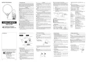
Test Lead Cap
:
Test leads can be used under the CAT.II and III environments by
attaching a Protective cap as illustrated below. Use of our Protective cap offers
differentlengthssuitableforthetestenvironments.
Barrer
Protectivefingerguard
:
It is a part providing protection against electrical shock and
ensuringtheminimumrequiredairandcreepagedistances.
Protective Cap