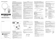
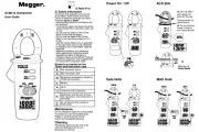
DIGITAL MULTIMETER
WITH
AC/DC CLAMP SENSOR
KEW MATE 2012RA
This instrument satisfies the marking requirement defined
in the WEEE Directive. This symbol indicates separate
collection for electrical and electronic equipment.
This marking means they shall be sorted out and collected
as ordained in DIRECTIVE.
This directive is valid only in the EU. When you remove
batteries from this product and dispose them, discard them
in accordance with domestic law concerning disposal. Take
a right action on waste batteries, because the collection
system in the EU on waste batteries are regulated.
# WARNING
●Measurement Category(CAT)
The restrictions on the maximum voltage level for which
the this product can be used, depend on the measurement
categories specified by the safety standards.
Do not apply any input level higher than maximum allowable
input.
AC/DC 600V CAT II AC/DC300V CAT III
CAT II
Appliances, portable equipment, ect. For measurements
performed on circuits directly connected to the low
voltage installation.
CAT III D i st ribu t i o n b oa r d , c i rcu i t bre a k e r, ec t . For
measurements performed in the building installation.
# DANGER
● Never make measurement on circuits with a maximum voltage
difference of 600V or greater between conductors (300V or
greater between a conductor and ground).
● Do not attempt to make measurement in the presence of
flammable gasses.
Otherwise, the use of the instrument may cause sparking,
which leads to an explosion.
● Never attempt to use the instrument if its surface or your hand
is wet.
● Do not exceed the maximum allowable input of measuring
ranges.
● Never open the battery compartment cover while making
measurement.
● Never try to make measurement if any abnormal conditions,
such as broken Clamp Sensor or case is noted.
● The instrument is to be used only in its intended applications or
conditions.
Otherwise, safety functions equipped with the instrument
doesnt work, and instrument damage or serious personal
injury may be caused.
1 SAFETY WARNINGS.
This instrument has been designed and tested according to
IEC Publication 61010: Safety Requirements for Electronic
Measuring Apparatus. This instruction manual contains warnings
and safety rules which must be observed by the user to ensure
safe operation of the instrument and to retain it in safe condition.
Therefore, read through these operating instructions before
starting using the instrument.
# WARNING
● Read through and understand instructions contained in this
manual before starting using the instrument.
● Save and keep the manual handy to enable quick reference
whenever necessary.
● Be sure to use the instrument only in its intended applications
and to follow measurement procedures described in the
manual.
● Be sure to understand and follow all safety instructions
contained in the manual.
Failure to follow the above instructions may cause injury, damage
to the instrument and/or damage to equipment under test.
The symbol # indicated on the instrument means that the user
must refer to related parts of the manual for safe operation of
the instrument. Be sure to carefully read the instructions following
each # symbol in this manual.
# DANGER:
is reserved for conditions and actions that are
likely to cause serious or fatal injury.
# WARNING:
is reserved for conditions and actions that can
cause serious or fatal injury.
# CAUTION:
is reserved for conditions and actions that can
cause minor injury or instrument damage.
Following symbols are used on the instrument and in the
instruction manual. Attention should be paid to each symbol to
ensure your safety.
#
Refer to the instructions in the manual.
This symbol is marked where the user must refer to the
instruction manual so as not to cause personal injury or
instrument damage.
Indicates an instrument with double or reinforced insulation.
Indicates that this instrument can clamp on bare conductors
when measuring a voltage corresponding to the applicable
Measurement category, which is marked next to this symbol.
Indicates AC (Alternating Current).
Indicates DC (Direct Current).
# WARNING
● Never attempt to make any measurement, if any abnormal
conditions are noted, such as broken case, cracked test leads
or Clamp Sensor Cable and exposed metal parts or internal
wiring.
● Do not turn the Function Selector Switch while the test leads
are connected to the circuit under test.
● Do not install substitute parts or make any modification to
the instrument. Return the instrument to Kyoritsu or your
distributor for repair or re-calibration.
● Do not try to replace the batteries if the surface of the
instrument is wet.
● Always disconnect the clamp sensor and the test leads
from the circuit under test and switch off the instrument
before opening the battery compartment cover for battery
replacement.
● A cap is provided on the tip of a test lead. Use a test lead with
the cap on for safety.
● Stop using the test lead if the outer jacket is damaged and the
inner metal or color jacket is exposed.
# CAUTION
● Make sure that the Function Selector Switch is set to an
appropriate position before making measurement.
● Always make sure to place the test leads in the holster before
making current measurement.
● Do not expose the instrument to the direct sun, extreme
temperatures or dew fall.
● This instrument isn't dust & water proofed. Keep away from
dust and water.
● Be sure to set the Function Selector Switch to the "OFF"
position after use. When the instrument will not be used for
a long period of time, place it in storage after removing the
batteries.
● Use a damp cloth and detergent for cleaning the instrument.
Do not use abrasives or solvents.
● Keep your fingers and hands behind the protective fingerguard
during measurement.
3 SPECIFICATIONS.
● Measuring Ranges and Accuracy (at 23 , relative ℃ ℃±5
humidity75% or less)
AC Current A (RMS value detection)
Maximum Input Current : 120A
Range Display range Allowable input Accuracy
60A 0.00
~60.39A 0.00~60.00Arms
(85Apeak or less) ±2.0%rdg±5dgt
(45~65Hz)
( )sine wave
120A 0.0~603.9A 0.0~120.0Arms
(170Apeak or less)
※ For non-sinusoidal waveforms, add ±(2% of reading + 2% of
full scale), for Crest factor<2.5.
DC Current A Maximum Input Current : 120A
Range Display range Allowable input Accuracy
60A ±0.00~60.39A ±0.00
~60.00A ±2.0%rdg±8dgt
120A ±0.0~603.9A ±0.0~120.0A ±2.0%rdg±5dgt
AC Voltage V (RMS value detection, Auto-range) Maximum Input Voltage : 600V
Range Display range Allowable input Accuracy
6V 0.000 ~6.039V
0.300~600.0Vrms
(850Vpeak or less)
±1.5%rdg±5dgt
(45~400Hz)
( )sine wave
60V 5.60~60.39V
600V 56.0~603.9V
※Input Impedance:approx. 10M <200pFΩ
※ For non-sinusoidal waveforms, add ±(2% of reading + 2% of
full scale), for Crest factor<2.5.
DC Voltage V (Auto-range) Maximum Input Voltage : 600V
Range Display range Allowable input Accuracy
600mV ±0.0~603.9mV
±0.0m~600.0V ±1.0%rdg±3dgt
6V ±0.560~6.039V
60V ±5.60~60.39V
600V ±56.0
~603.9V
※Input Impedance:approx. 10MΩ
Resistance (Auto-range)Ω
Range Display range Allowable input Accuracy
600 0.0Ω~603.9Ω
0.0Ω~60.00MΩ
±1.0%rdg±5dgt
6k 0.560Ω~6.039kΩ
60k 5.60Ω~60.39kΩ
600k 56.0Ω~603.9kΩ
6MΩ
0.560~6.039MΩ
±2.0%rdg±5dgt
60M 5.60Ω~60.39M ±3.0%rdg±5dgtΩ
※ Open-loop Voltage:approx.0.6V, Measuring Current : 0.3mA or
less
Continuity
Range Display range Allowable input Accuracy
600 0.0Ω~603.9 0.0Ω~600.0 ±1.0%rdg±5dgtΩ
※ ΩThe buzzer turns on for resistances lower than 35±25 .
※ Open-loop Voltage:approx.0.6V, Measuring Current : 0.3mA
or less
Diode
Range Display range Allowable input Accuracy
2V 0.000
~1.999V 0.000~1.999V ±3.0%rdg±5dgt
※Open-loop Voltage:approx.2.7V
Capacitor (Auto-range)
Range Display range Allowable input Accuracy
40nF 0.00
~40.39nF the accuracy is not guaranteed
400nF 36.0~403.9nF
40.0n
~40.00 Fμ
±2.5%rdg±10dgt4 F 0.360μ~4.039 Fμ
40 F 3.60μ~40.39 Fμ
400 F 36.0μ~403.9 Fμ
the accuracy is not guaranteed
4000 F 360μ~4039 Fμ
Frequency Hz ( AC Current ) (Auto-range)
Range Display range Allowable input Accuracy
10Hz 0.000~9.999Hz The accuracy is not guaranteed
100Hz 9.00
~99.99Hz 9.00Hz~400.0Hz ±0.2 rdg±2dgt%
1000Hz 90.0~400.0Hz ±0.1 rdg±1dgt%
400.1~999.9Hz
The accuracy is not guaranteed
10kHz 0.900
~9.999kHz
100kHz 9.00~99.99kHz
1000kHz 90.0~999.9kHz
10MHz 0.900~9.999MHz
※Input Current:more than 6A
Frequency Hz ( AC Voltage ) (Auto-range)
Range Display range Allowable input Accuracy
10Hz 0.000~9.999Hz The accuracy is not guaranteed
100Hz 9.00
~99.99Hz
9.00Hz~300.0kHz
±0.2 rdg±2dgt%
1000Hz 90.0
~999.9Hz
±0.1 rdg±1dgt%
10kHz 0.900
~9.999kHz
100kHz 9.00~99.99kHz
300kHz 90.0~300.0kHz
1000kHz 300.1~999.9kHz The accuracy is not guaranteed
10MHz 0.900~9.999MHz
※ Input Voltage:more than 6V (~10kHz) , more than 20V (10k
~300kHz)
※Input Impedance:approx. 900kΩ
Note:◇ The symbol of " ―" in the above table means that the
instrument only displays the value, but the accuracy, the
proper operation and the safety are not guaranteed.
2 FEATURES.
● Permits AC/DC current measurement up to 120A using a
clamp sensor that comes standard with the instrument
● Clamp sensor for ease of use in crowded cable areas and
other tight places
●
Permits current measurement with an open current-clamp sensor
that does not require opening and closing operations by the user
●True-RMS measurements ACV and ACA.
●Auto-power-save function
●Buzzer for easy continuity checking
●Data hold function to freeze the readings
●LCD with a bar graph
●Shock absorbing holster for ease of storage
●
Designed to international safety standard IEC61010-1: over-voltage
category CAT III 300V, CAT II 600V and pollution degree 2.
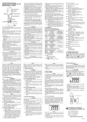
[ Effective Value (RMS) ]
Most alternating currents and voltages are expressed in
effective values, which are also referred to as RMS (Root-Mean-
Square) values.
The effective value is the square root of the average of square
of alternating current or voltage values. Many clamp meters
using a conventional rectifying circuit have "RMS" scales for AC
measurement. The scales are, however, actually calibrated in
terms of the effective value of a sine wave though the clamp
meter is responding to the average value. The calibration is
done with a conversion factor of 1.111 for sine wave, which
is found by dividing the effective value by the average value.
These instruments are therefore in error if the input voltage or
current has some other shape than sine wave.
[ CF (Crest Factor) ]
CF (Crest Factor) is found by dividing the peak value by the
effective value.
Examples: Sine wave: CF=1.414
Square wave with a 1: 9 duty ratio: CF=3
●Safety Standard
IEC 61010-1, 61010-2-032, 61010-2-033
CAT III 300V, pollution degree 2
CAT II 600V, pollution degree 2
IEC 61010-031
EN 61326-1 (EMC)
EN 50581 (RoHS)
● ΔΣOperating System modulation
●Display Liquid crystal display
Maximum Reading:6039
Except Hz : 9999, CAP : 4039,
Diode : 1999
Bar graph with maximum points of 30.
●Display approx. 3 times per second
Indication renewal
●Location for use
Indoor use, 2000m max, above sealevel
●
Operating Temperature
0 ~ +40 , relative humidity 85% or less℃
and Humidity Range (without condensation)
●Storage Temperature
-20 ~ +60 , relative humidity 85% or less℃
and Humidity Range (without condensation)
●Source Two 1.5VDC R03 (UM-4) batteries
●Current Consumption approx. 3mA (DCV), approx. 13mA
(ACA)
●Power-save Function Shifts to the power-save state about
15 min ut es af ter t he last switch
operation.
●Low battery warning Appears when the batteries
become low (2.4±0.15V or less)
●Overload Protection AC voltage / DC voltage / Frequency
ranges :
DC / ACrms 720V for 10 seconds
AC current / DC current ranges :
DC / ACrms 150A for 10 seconds
Resistance / Continuity / Diode /
Capacitor ranges :
DC / ACrms 600V for 10 seconds
●Withstand Voltage AC3470Vrms for 5 seconds between
electrical circuit and housing case
● ΩInsulation Resistance 100M or greater at 1000V
between electrical circuit and housing
case
● φConductor Size Approx. 12mm diameter max
●Dimensions 128(L)×92(W)×27(D)mm
●Weight Approx. 220g
●Accessories Two R03 (UM-4) batteries
Instruction Manual
INSTRUCTION MANUAL
Waveform
Crest factor
CF
Average value
Vavg
Effective value
Vrms
Conversion
factor
Vrms/ Vavg
Reading errors for
average sensing
instrument
≒ ≒0.637 1.111 ≒1.414
≒1.155 ≒1.732
= %-3.8
× %100
= %11.1
≒0.707
2
1
22
π
A
3
D
13
2
D
1
3
A
0.5A 1.111-×3
A
A
A A
A
1
0.5A
1
0%
2A
π
=
AD
f
A A= ・D
T
2
A
A 1,111-A××100
×100
DA
D
1
=
A
DA
( 1.111 -1)
D
A
0
A
0
A
0
A
0
T
D=f/T
f
3
DISTRIBUTOR
Kyoritsu reserves the rights to change specifications
or designs described in this manual without notice
and without obligations.
6-18 92-2316A