Legrand RH250W Manual
Legrand
Ikke kategoriseret
RH250W
| Mærke: | Legrand |
| Kategori: | Ikke kategoriseret |
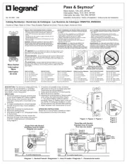
| Model: | RH250W |
Har du brug for hjælp?
Hvis du har brug for hjælp til Legrand RH250W stil et spørgsmål nedenfor, og andre brugere vil svare dig
Ikke kategoriseret Legrand Manualer
15 Juli 2025

7 Juli 2025
7 Juli 2025
7 Juli 2025

28 Marts 2025

1 Oktober 2024

1 Oktober 2024

1 Oktober 2024
6 September 2024

28 August 2024
Ikke kategoriseret Manualer
- Ernitec
- G-LAB
- Avantone Pro
- Globe
- Doro
- Spektrum
- RADEMACHER
- Vinten
- Bredemeijer
- Vaxis
- Deaf Bonce
- Greenworks
- AvaValley
- Airlux
- AudioThing
Nyeste Ikke kategoriseret Manualer

7 December 2025

7 December 2025

7 December 2025

7 December 2025

7 December 2025

7 December 2025

7 December 2025

7 December 2025

7 December 2025

7 December 2025