Legrand 310877 Manual


Læs gratis den danske manual til Legrand 310877 (4 sider) i kategorien Ikke kategoriseret. Denne vejledning er vurderet som hjælpsom af 3 personer og har en gennemsnitlig bedømmelse på 4.6 stjerner ud af 2 anmeldelser. Har du et spørgsmål om Legrand 310877, eller vil du spørge andre brugere om produktet?

Side 1/4
LEGRAND - Pro and Consumer Service - BP 30076 - 87002 LIMOGES CEDEX FRANCE – www.legrand.com 09/18-01 GF
LE05874AD
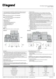
Manual Bypass Megaline/1 and Megaline/2
3 108 77 – 3 108 78
L
N
PE
L
N
PE
IN
N
PE
L
OUT
L
PE
N
IN
EPO
MEGALINE/1 MEGALINE/2
Essai initial
Brancher le câble d’entrée au secteur, une charge de signal à la sortie (par exemple une
lampe) et l’EPO (normalement fermé – NF). Avec l’onduleur éteint, s’assurer que :
- si l’interrupteur est sur la position I (voyant jaune allumé), la charge est alimentée ;
- si l’interrupteur est sur la position 0 (voyant jaune éteint), la charge n’est pas alimentée ;
- appuyer sur le bouton EPO et s’assurer que l’onduleur s’éteint.
Allumer l’onduleur et s’assurer que la charge est toujours alimentée, que l’interrupteur
soit sur l’une ou l’autre des deux positions. Si tel n’est pas le cas, contrôler le
branchement des câbles, la tension d’alimentation sur secteur et s’assurer que la prise
de l’unité de by-pass est bien branchée.
Mode d’utilisation normal
Quand l’onduleur est utilisé en mode normal, maintenir l’interrupteur du by-pass en
position 0 et le contact EPO fermé.
ATTENTION : Ne jamais laisser l’interrupteur dans la position I pendant le mode
d’utilisation normal. En cas de coupure de l’alimentation sur secteur, l’onduleur n’est
pas branché à la sortie.
Mode d’utilisation service/maintenance
Pour débrancher l’onduleur :
- placer l’interrupteur du by-pass sur la position I.
- éteindre l’onduleur.
- retirer les vis de fixation de l’unité de by-pass et retirer le by-pass du connecteur de
l’onduleur.
ATTENTION : dans cette condition, les charges sont alimentées directement sur
secteur. En plaçant l’interrupteur sur la 0, l’alimentation de la charge est coupée.
Pour rebrancher l’onduleur :
- remettre en place l’unité de by-pass (voir point 8 de l’installation).
- allumer l’onduleur.
- placer l’interrupteur du by-pass sur la position 0.
Caractéristiques techniques
3 108 77
Megaline/1 By-pass
3 108 78
Megaline/2 By-pass
Tension d’entrée 184 - 265V 184 - 265V
Tension de sortie 184 - 265V 184 - 265V
Courant d’entrée et sortie 23 A max 44 A max
Puissance commutable 5000VA 10000VA
Fusibles de protection 1 pc 10x38 aR 32A 600V 2 pcs 10x38 aR 40A 600V
Degré de protection IP 20 IP 20
Dimensions 240x145x59 mm 240x145x59 mm
Le by-pass manuel permet de débrancher et de rebrancher l’onduleur à la charge sans
coupures d’alimentation. Il est de la sorte possible de proder aux interventions de
maintenance sur l’onduleur sanssagment pour l’utilisateur.
Le by-pass manuel 3 108 77 doit être instal UNIQUEMENT
avec les onduleurs Megaline/1.
Le by-pass manuel 3 108 78 doit être instal UNIQUEMENT
avec les onduleurs Megaline/2.
Contenu de l’emballage :
1 By-pass manuel
1 Fiche des instructions
1 Instructions decurité en plusieurs langues
2 vis tarauds à tête cylindrique 2,9 x 9,5
2 vis tarauds à tête cylindrique 3,9 x 9,5
2 vis tarauds à tête évasée 2,9 x 9,5
6 vis M 3 x 10
1 couvercle
Installation :
L’installation doit être confe à un technicien qualif.
1. Éteindre l’onduleur.
2. brancher le câble d’alimentation sur secteur et le câble de sortie des charges.
3. Retirer le connecteur des branchements au dos de l’onduleur en dévissant les deux
vis de fixation. Conserver les vis. Sur Megaline/1, deux vis M4 x 60 sont psentes. Sur
Megaline/2, deux vis M4 x 70 sont psentes.
4. brancher les deux câbles de la prise interne du connecteur (elles doivent ensuite être
utilisées pour le branchement à l’unité de by-pass).
5. Brancher le câble d’ente et le câble de sortie au bornier en respectant les indications
IN/OUT ainsi que celles de phase et de neutre. Serrer les bagues des serre-câbles une fois
le branchement effectué.
6.
- Megaline/1 (3 108 77) : brancher les câbles EPO (double isolation) aux deux pôles du connecteur
vert pourvus de vis. Serrer la bague du serre-ble une fois le branchement effectué ;
- Megaline/2 (3 108 78) : brancher les câbles EPO (double isolation) au connecteur à 2 pôles.
Serrer la bague du serre-ble une fois le branchement effectué.
7. - Megaline/1 (3 108 77) : mettre en place le couvercle et le fixer avec deux vis tarauds à
te évae 2,9 x 9,5 ;
- Megaline/2 (3 108 78) : mettre en place le couvercle et le fixer avec six vis M3 x 10.
8. Brancher l’uni de by-pass à l’onduleur et la fixer avec les deux vis du connecteur
précédemmentbranc.
9. - Megaline/1 (3 108 77) : fixer la base du by-pass au châssis à l’aide de deux vis tarauds à
te cylindrique 2,9 x 9,5 ;
- Megaline/2 (3 108 78) : fixer la base du by-pass au châssis à l’aide de deux vis tarauds à
te cylindrique 3,9 x 9,5.
2
The manual bypass enables the disconnection and reconnection of the UPS to the
protected load without any interruption of the power supply. It is possible therefore to
service the UPS with no downtime and therefore without causing any inconvenience
to the user.
The manual bypass 3 108 77 must be installed ONLY with UPS Megaline/1
The manual bypass 3 108 78 must be installed ONLY with UPS Megaline/2
Box contents:
1 pc Manual bypass
2 pcs self threading pan head screws 2.9 x 9.5
2 pcs self threading pan head screws 3.9 x 9.5
2 pcs self threading countersunk head screws 2.9 x 9.5
6 pcs screws M 3 x 10
1 pc cover
1 pc Instruction sheet
1 Multilanguage safety instructions
Installation:
The manual bypass must be installed by qualified technical personnel.
1. Switch off the UPS.
2. Disconnect the UPS input cable from the mains supply and the UPS output cable
from the load.
3. Remove the connection terminal block on the rear of the UPS by unscrewing the
two screws. Save the screws. There are two M4 x 60 screws in the Megaline/1. There
are two M4 x 70 in the Megaline/2.
4. Unwire the two cables from the connection terminal block since they will be used to
connect the UPS to the bypass.
5. Connect the input wire and the output wire to the connector taking care to to
respect the indications references of IN/OUT, phase and neutral. Then tighten the
cable guide ring nuts.
6. - Megaline/1 (3 108 77): Connect EPO cables (double insulation) to the 2 poles of
green connector provided with screws. Then tighten the cable gland;
- Megaline/2 (3 108 78): connect EPO cables (double insulation) to the 2 poles
connector. Then tighten the cable gland.
7. - Megaline/1 (3 108 77): fix the cover with two self threading countersunk head
screws 2.9 x 9.5;
- Megaline/2 (3 108 78): fix the cover with six M3 x 10 screws.
8. Install the bypass onto the UPS by fixing it with the two screws taken from the
terminal block previously removed.
9. - Megaline/1 (3 108 77): fix the base of the bypass to the UPS cabinet with two self
threading pan head screws 2.9 x 9.5;
- Megaline/2 (3 108 78): fix the base of the bypass to the UPS cabinet with two self
threading pan head screws 3.9 x 9.5.
MEGALINE/1 MEGALINE/2
Test
Connect the input cable to the mains power supply, connect a load to the UPS output
(e.g. a lamp) and the EPO (Normally Closed - NC). With the UPS switched off, check the
following:
- bypass switch in position I (yellow light on) - the load receives power;
- bypass switch in position 0 (yellow light off) - the load receives no power;
- push the EPO button and check that the UPS switches off.
Switch on the UPS and check that the load receives power when the bypass switch is
in both positions. If this does not take place, check the connection of the cables, the
supply voltage rating and that the bypass is fully inserted into the UPS socket.
Use of the bypass in normal operating conditions
When the UPS is operating in normal conditions, the bypass switch must remain in
position 0 and EPO contact closed.
NOTE: Never leave the bypass switch in position I during normal UPS operation: the
load is not protected in case of a mains supply blackout because the UPS output is
not connected.
Use of the bypass for service
To disconnect the UPS:
- commute the bypass switch to position I.
- switch off the UPS.
- Unscrew the fixing screws on the bypass and then remove the bypass from the UPS
socket.
NOTE: the load now receives power directly from the mains power supply. If the
bypass switch is put to position 0, the power supply to the load will be interrupted.
To reconnect the UPS:
- replace the bypass into the UPS socket (refer to point 8 of the installation
procedure).
- switch on the UPS.
- commute the bypass switch to position 0.
Technical data
3 108 77
Megaline/1 Bypass
3 108 78
Megaline/2 Bypass
Input Voltage 184 - 265V 184 - 265V
Output Voltage 184 - 265V 184 - 265V
Input & Output current 23 A max 44 A max
Max UPS power 5000VA 10000VA
Protection Fuses 1 pc 10x38 aR 32A 600V 2 pcs 10x38 aR 40A 600V
Degree of Protection IP 20 IP 20
Size 240x145x59 mm 240x145x59 mm
L
N
PE
L
N
PE
IN
N
PE
L
OUT
L
PE
N
IN
EPO


Produkt Specifikationer

Mærke: Legrand
Kategori: Ikke kategoriseret
Model: 310877
Vægt: 570 g
Produktfarve: Sort
Produkttype: Bypass-afbryder
Kapabilitet: Megaline

Har du brug for hjælp?

Hvis du har brug for hjælp til Legrand 310877 stil et spørgsmål nedenfor, og andre brugere vil svare dig