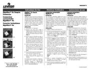
Leviton 499SC Manual
Leviton
Ikke kategoriseret
499SC
Læs nedenfor 📖 manual på dansk for Leviton 499SC (2 sider) i kategorien Ikke kategoriseret. Denne guide var nyttig for 2 personer og blev bedømt med 4.2 stjerner i gennemsnit af 1.5 brugere
Side 1/2

FASTSPLICE
®
LC, SC, and ST Connectors for 900 m Fiber
Cat. Nos. 499LC, 499SC, and 499ST
INSTALLATION INSTRUCTIONS
ENGLISH
WARNINGS:
• Read and understand all instructions. Follow all warnings and instructions
marked on the product.
• Disconnected optical components may emit invisible optical radiation that can
damage your eyes. TO AVOID PERSONAL INJURY, never look directly into an
optical component that may have a laser coupled to it. If accidental exposure to
laser radiation is suspected, consult a physician for an eye examination.
• The ferrule component of this product has exposed bare ber. Use extreme
caution when handling.
CAUTIONS:
• Isopropyl alcohol is ammable and can cause eye irritation on contact. If eye contact occurs, ush with water for at least
15 minutes. In case of ingestion, consult a physician. Use only in well-ventilated areas.
• Wearing safety glasses during installation of this device is recommended. Although standard safety glasses provide no
protection from potential optical radiation, they offer protection from accidental airborne hardware and cleaning solvents.
• Fiber optic cable is sensitive to excessive pulling, bending, and crushing forces. Do not bend the cable less than the
recommended minimum bend radius. Do not use more pulling force on the cable than specied. Do not kink or
crush cable.
• SAVE THESE INSTRUCTIONS.
Tools Required:
• FASTSPLICE Universal LC/SC/ST ferrule
holder - included in the Leviton Splice-On
Connector Tool Kit (sold separately). Also sold
individually (Cat. No. 49886-SH1).
• Fine-tipped felt pen
• Millimeter scale, or use the marking
templates in Step 3
• Fiber stripper
• 99% Isopropyl alcohol
• Lint-free wipes
• Precision cleaver
• Fusion splicer, with appropriate accessories.
Leviton Recommended Tool Kit:
Splice-On Connector (SOC) Tool Kit
(Cat. No. 49800-SOC) - Includes all the tools
you will need for this installation:
• Leviton FASTSPLICE Universal LC/SC/ST
ferrule holder (10 pk)
• 2 mm cable clamp
• 3 mm cable clamp
• 250/900 μm cable clamp
• Lint-free wipes (100 pk)
• Safety pad
• 250/900 μm ber stripper
• Kevlar
®
aramid ber shears
• Armored cable cutter
• Slitting tool
• Mini ber optic disposal bin w/ slide
• Fiber tube scorer 1.6-6.0 mm
• Fiber preparation uid PNM- FPF
Before Installation
Installation
1. If using a fan out kit, place a 900 um clamp on the cable.
a. Install the appropriate cable clamp approximately 10 in. from the end of the cable.
b. Engage the clamp.
NOTE: This step is not applicable to 900 μm tight buffer bers. Use the cable clamp only when
terminating 250 μm coated bers with a 900 um buffer tube (e.g., when using a fan-out kit).
2. Add a boot and sleeve to the cable.
a. Slide the 900 μm boot, followed by the protective sleeve, onto the cable.
3. Prepare the ber for cleaving.
a. On a at, clean surface, use a ne-tipped felt pen to place a mark 35 mm from the end of
the cable jacket. Use a milimeter scale or the template below.
b. Remove the 900 μm buffer to the 35 mm mark.
c. Clean the stripped ber with an alcohol wipe, to remove any debris.
4. Perform a precision cleave.
NOTE: A maximum cleave length of 10 mm is required to position the exposed ber under the
splice sleeve after heat shrinking. Prior to cleaving, verify that a 10 mm cleave will be performed
for ber holders and precision cleavers by manufacturer.
a. Place the stripped ber into the ber holder so that the end of the 900 μm buffer is at the exit
point of the ber holder, or at the appropriate position to provide a maximum 10 mm cleave
length. Then, close the ber holder clamp.
b. Load the ber holder into a precision cleaver.
c. Perform the precision cleave and then properly dispose of any ber shards.
d. Carefully remove the ber holder from the precision cleaver and then load it into the left side
of the fusion splicer.
5. Prepare the ferrule unit for fusion splicing.
Load the ferrule into the FASTSPLICE Universal ferrule holder and then close the a.
hinge door.
Load the ferrule unit into the right side of the fusion splicer.b.
6. Perform a fusion splice.
a.
Verify that the bers are properly seated in the V-grooves and then close the wind protector.
Perform the fusion splice, in accordance with the fusion splicer manufacturer's instructions.b.
c. Verify an acceptable insertion loss value and, if not an automated step in the splicer, perform
a tension test.
Boot
Cable Clamp
Sleeve
10 in.
(Not to scale)
Perform all setup, maintenance, and preparation steps, as required by the fusion splicer manufacturer’s instructions, prior to termination.
Fiber type (SM, MM) and splice sleeve heater settings must be correctly entered for proper termination.
Fiber Holders or Sheath Clamps and Cable Clamps: Properly secure the raw ber cable on the left side of the fusion splicer. Verify that the correct ber
holder is being used for cable construction, by splicer manufacturer and model. Cable clamps are also required when using fan out kits and any loose tube
construction during termination, to prevent ber pistoning. UCL Swift Splicers require holder UCL SWIFT PN: F-20/30.
Fusion Splice Settings: “Auto” (by ber type) is a common acceptable setting for most splicers. To account for pre-positioning and travel of motors, some
devices have pre-congured Splice-On Connector (SOC) settings. Consult the user guide and setup menu of the device in use for available settings.
NOTE: For typical fusion splice programs that are applicable by the manufacturer, see the Fusion Splice Programs table.
Heater Settings: To account for the use of smaller form factor heat shrink sleeves, many current devices have pre-congured heater settings. For older units
that do not specically address splice-on connectors, a standard shrink tube of similar length can typically be used. If sleeves are over or under-heated, a
custom heater program may be required. Leviton recommends testing the heater performance by using a target splice sleeve with bulk tight-buffered ber, and
adjusting the heat duration and/or temperature accordingly prior to termination.
CAUTION: Settings may vary by specic splicer manufacturer and model. Refer to heater settings menu by splicer. While heat cycle duration may be
extended, it is NOT recommended to increase heating temperatures ABOVE the settings listed in the second table on the right.
Cable
Dot is Facing UP Ferrule
Ferrule
Holder
Fiber Holder
Hinge Door
(Zero Mark)
35 mm
Bare Fiber
End of
Stripped
Fiber
900 μm
Tight
Buffer
Ferrule HolderFiber Holder
Recommended Heater Settings
900 µm Connectors
Utiliz
es 27 mm splice sleeves
MFG Model Mode Title Temperature Time
AFL
90s
Custom
410°F (210°C) 30 seconds
70s Custom 464°F (240°C) 30 seconds
41s/31s Custom 446°F (230°C) 45 seconds
Sumitomo
T-Q102-CA Lynx 374°F (190°C) 35 seconds
T-Q502-S Lynx 374°F (190°C) 34 seconds
Fitel
S179 SOC EZFuse 338°F (170°C) 50 seconds
Ninja NJ001
Custom
338°F (170°C) 80 seconds
UCL Swift
KF4 / KF4A
Custom
383°F (195°C) 45 seconds
K11
Custom
383°F (195°C) 45 seconds
Fusion Splice Programs
MFG Model Common Settings
AFL
90s
"“SM AUTO” for Single mode
“MM AUTO” for Multi-mode"
70s
41s/31s
Sumitomo
T-Q102-CA
Select “Auto” and then “Auto” - or
- Single mode “SM G652 Auto”;
Multi-mode “MM G651 Auto”
T-Q502-S
Fitel
S179
(example S179) Setting 064 “AFL
SOC SM” for Single mode; Setting
065 “AFL SOC MM” for Multi-mode
Ninja
NJ001
UCL Swift
KF4 / KF4A
(example KF4A) Setting 6 “SM
Quick” for Single mode; Setting 8
“MM Quick” for Multi-mode
K11
RECOMMENDED: Scan the QR code located on the outer packaging for an expansive list of fusion splicer makes and models, ber holder part
numbers, fusion splice settings, and heater settings. Please refer to the splicer manufacturer User Manual or Leviton Applications Note
NSAN-19-0003-090919 for instructions on creating custom heater programs.
PK-A3295-10-00-0C

© 2023 Leviton Mfg. Co., Inc.
For LC Termination: For SC Termination: For ST Termination:
a. Slide the boot over the protective sleeve Slide the boot/spring over the protective sleeve..a.a. Slide boot/spring over the protective sleeve.
b. Hold the base and remove the grip. Hold the base and remove the grip.b.b. Hold the base and remove the grip.
c. Add connector housing. Align tab on boot with
key/opening on connector body. Press boot
assembly onto housing until a click is heard.
NOTE: For APC (green) connectors, align the red dot on the
ferrule assembly, with the white dot on the boot assembly key
and the key/opening in the connector housing.
c. Add connector body. Align 1 (triangle) to 2 (tab),
then connect 1 and 2 to 3. Press boot assembly
onto housing until a click is heard.
NOTE: For APC (green) connectors, align the red dot on the
ferrule assembly, with the white dot on the boot assembly key
and the key/opening in the connector housing.
c. Add connector housing. Align 1 into 2, verify
ferrule assembly is inserted fully through
connector housing. Connect 1 and 2 to 3 by
pressing boot assembly onto housing until a click
is heard.
d. Add connector housing. Push until you hear
a click.
e. Add connector cap.
d. Add a connector cap.
d. If not installed, add a connector cap.
Termination is complete.
7. Slide the sleeve over the splice point.
a. Slide the splice sleeve towards the left ber holder and open the wind protector.
b. While maintaining gentle tension, open the connector holder and ber holder doors and
remove the spliced assembly from the splicer.
c. While maintaining gentle tension, slide the splice sleeve over the splice point until it is ush
with the ferrule unit.
8. Heat the protective sleeve.
a. Lift the ber and connector grip and then position the splice assembly into the center of the
heating unit.
b. Heat the protective sleeve in accordance to the manufacturer's instructions.
WARNING: Allow time for the sleeve to cool before removing from the heater.
Match Grooves
Base GripGripGrip
Connector CapConnector Cap
Front of
Connector housing.
Front of
Connector
BaseBase
Align
Align
2 231 1
FOR CANADA ONLY
For warranty information and/or product returns, residents of Canada should contact Leviton in writing at Leviton Manufacturing of Canada ULC to the attention of the Quality Assurance Department,
165 Hymus Blvd, Pointe-Claire (Quebec), Canada H9R 1E9 1 -800-405-5320. or by telephone at
INDUSTRY CANADA COMPLIANCE STATEMENT:
This device complies with Industry Canada license-exempt RSS standard(s). Operation is subject to the following two conditions: (1) this device may not cause interference, and (2) this device must accept any interference, including
interference that may cause undesired operation of the device. IMPORTANT! Any changes or modications not expressly approved by the party responsible for compliance could void the user’s authority to operate this equipment.
This Class A digital apparatus complies with Canadian CAN ICES-3(A)/NMB-3(A).
Patents covering this product, if any, can be found on www.leviton.com/patents.
TRADEMARK DISCLAIMER: Use herein of third party trademarks, service marks, trade names, brand names and/or product names are for informational purposes only, are/may be the trademarks of their respective owners; such use is not
meant to imply afliation, sponsorship, or endorsement.
Sleeve
Leviton, and Leviton Block Design are trademarks of Leviton Manufacturing Co., Inc. and are registered trademarks in many countries throughout the world. FASTSPLICE is a trademark of Leviton
Manufacturing Co., Inc. and is registered in the United States.
Align
Front of
Connector housing
Front of
Ferrule assembly
Align
23 1
For Technical Assistance Call: 1-800-824-3005 (USA Only) or 1-800-405-5320 (Canada Only) www.leviton.com
LIMITED 1 YEAR PRODUCT WARRANTY
For Leviton’s limited 1 year product warranty, go to www.leviton.com. For a printed copy of the warranty you may call 1-800-323-8920 or write to Leviton Manufacturing Co., Inc., Att: Customer Service Dept., 201 North Service Road, Melville,
New York 11747.
Produkt Specifikationer
Mærke: | Leviton |
Kategori: | Ikke kategoriseret |
Model: | 499SC |
Har du brug for hjælp?
Hvis du har brug for hjælp til Leviton 499SC stil et spørgsmål nedenfor, og andre brugere vil svare dig
Ikke kategoriseret Leviton Manualer

8 Juni 2025

7 Juni 2025

7 Juni 2025

6 Juni 2025

3 Juni 2025

28 December 2024

5 September 2024

1 September 2024

1 September 2024

1 September 2024
Ikke kategoriseret Manualer
- Ikke kategoriseret Asetek
- Ikke kategoriseret Twinkly
- Ikke kategoriseret Grüniq
- Ikke kategoriseret Elro
- Ikke kategoriseret Prem-i-air
- Ikke kategoriseret Kramer
- Ikke kategoriseret Hogue
- Ikke kategoriseret Sanitas
- Ikke kategoriseret Merax
- Ikke kategoriseret XFX
- Ikke kategoriseret Healthy Choice
- Ikke kategoriseret Blackmagic Design
- Ikke kategoriseret Venom
- Ikke kategoriseret Vision
- Ikke kategoriseret Keurig
Nyeste Ikke kategoriseret Manualer

8 Juni 2025

8 Juni 2025

8 Juni 2025

8 Juni 2025

8 Juni 2025

8 Juni 2025

8 Juni 2025

8 Juni 2025

8 Juni 2025

8 Juni 2025