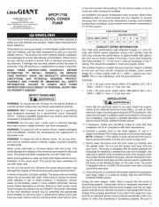
Little Giant 20E-CIM Manual


Læs gratis den danske manual til Little Giant 20E-CIM (8 sider) i kategorien Vandpumpe. Denne vejledning er vurderet som hjælpsom af 4 personer og har en gennemsnitlig bedømmelse på 4.5 stjerner ud af 2.5 anmeldelser. Har du et spørgsmål om Little Giant 20E-CIM, eller vil du spørge andre brugere om produktet?

Side 1/8
INTRODUCTION
EN
This instruction sheet provides you with the information required to safely own
and operate your product. Retain these instructions for future reference.
The product you have purchased is of the highest quality workmanship and
material, and has been engineered to give you long and reliable service. This
product has been carefully tested, inspected, and packaged to ensure safe
delivery and operation. Please examine your item(s) carefully to ensure that no
damage occurred during shipment. If damage has occurred, please contact the
place of purchase. They will assist you in replacement or repair, if required.
INSTALL, OPERATE, OR SERVICE YOUR PRODUCT. KNOW THE PRODUCT’S
APPLICATION, LIMITATIONS, AND POTENTIAL HAZARDS. PROTECT
YOURSELF AND OTHERS BY OBSERVING ALL SAFETY INFORMATION.
FAILURE TO COMPLY WITH THESE INSTRUCTIONS COULD RESULT IN
PERSONAL INJURY AND/OR PROPERTY DAMAGE!
DESCRIPTION
Little Giant Submersible 20S Series Sewage Ejector Pumps and 20E Series Effluent
Pumps are recommended for use in basins or lift stations and suitable for pump-
ing sewage, effluent, wastewater and other non-explosive, non-corrosive liquids.
The S Series Sewage Ejector Pumps have 2" spherical solids handling capability.
The E Series Effluent Pumps have 3/4" spherical solids handling capability.
Little Giant offers a complete line of float switches and liquid level control sys-
tems for automatic operation along with a complete line of alarms, basins, cov-
ers, and check valves.
SPECIFICATIONS
Discharge Size: 20E and 20S 2" or 3"
Handling Capabilities: E Series 3/4" spherical solids
S Series 2" spherical solids
Pump Housing: Cast iron
Volute: Cast iron
Impeller: Non-clog brass with pressure relief vanes
Motor: 3200 RPM with automatic overload protection
Hardware: 300 Series stainless steel
Bearing: Ball
Shaft Seal: Mechanical, spring loaded, rotating carbon with Nitrile
boot and stationary ceramic seat, with secondary Nitrile
exclusion seal
Power Cord: 14 AWG 3-conductor, copper, stranded
Cooling: The motor housing contains a cooling oil to provide
cooling for the motor and to lubricate bearings and
seals. These pumps are capable of operating with the
motor housing partially exposed for extended periods
of time, providing sufficient motor cooling and bearing
lubrication. However, for the best cooling and longest
motor life, the liquid level being pumped should normally
be above the top of the cast iron motor housing.
SAFETY GUIDELINES
WARNING: RISK OF ELECTRIC SHOCK. This pump is supplied with a ground-
ing conductor and grounding-type attachment plug. To reduce the risk of electric
shock, be certain that it is connected only to a properly grounded, grounding-
type receptacle.
When a pump is in a basin, etc., do not touch motor, pipes or water until unit is
unplugged or shut off. If your installation has water or moisture present, do not
touch wet area until all power has been turned off. If shut-off box is not acces-
sible, call the electric company to shut off service to the house, or call your local
fire department for instructions. Failure to follow this warning can result in fatal
electrical shock.
The flexible jacketed cord assembly mounted to the pump must not be modified
in any way, with the exception of shortening the cord to fit into a control panel.
Any splice between the pump and the control panel must be made within a
junction box and mounted outside of the basin, and comply with the National
Electrical Code. Do not use the power cord for lifting the pump.
The pump motor is equipped with an automatic resetting thermal protector and
may restart unexpectedly. Protector tripping is an indication of motor overload-
ing as a result of operating the pump at low heads (low discharge restriction),
excessively high or low voltage, inadequate wiring, incorrect motor connections,
or a defective motor or pump.
Read all instructions and Safety Guidelines thoroughly. Failure to follow the
guidelines and instructions could result in serious bodily injury and/or property
damage.
DO NOT USE TO PUMP FLAMMABLE OR EXPLOSIVE FLUIDS SUCH AS
GASOLINE, FUEL OIL, KEROSENE, ETC. FAILURE TO FOLLOW THIS WARNING
CAN RESULT IN PERSONAL INJURY AND/OR PROPERTY DAMAGE.
During normal operation the sump pump is immersed in water. Also, during rain
storms, water may be present in the surrounding area of the pump. Caution must
be used to prevent bodily injury when working near the pump:
Electrical power should be disconnected prior to touching, servicing or
repairing the pump.
To minimize possible fatal electrical shock hazard, extreme care should be
used when changing fuses. Do not stand in water while changing fuses or
insert your finger into the fuse socket.
Do not run the pump in a dry basin. If the pump is run in a dry basin, the surface
temperature of the pump will rise to a high level. This high level could cause skin
burns if the pump is touched and will cause serious damage to your pump.
Do not oil the motor. The pump housing is sealed. A high grade dielectric oil
devoid of water has been put into the motor housing at the factory. Use of other
oil could cause serious electric shock and/or permanent damage to the pump.
Do not install in locations classified as hazardous in accordance with the National
Electrical Code, ANSI/NFPA 70.
INSTALLATION
For automatic operation, pump must be plugged or wired into a remote float
switch or liquid level controller. Installation instructions are included with all Little
Giant switches and controllers and should be referred to for installation.
Pump will run continuously if plugged directly into an electrical outlet. Care
should be taken to prevent pump running in a dry sump.
Pump must be installed in a suitable gas tight basin which is at least 24" in diam-
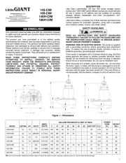
20E-CIM
20S-CIM
1 Phase
Figure 1
MODEL
NO.
CATALOG
NO. HP PH VOLTS HZ AMPS
GPM @ HEAD
SHUT
OFF (Ft.)
POWER
CORD (ft.)
WEIGHT
(lbs.)10’ 20’ 30’ 40’ 60’ 80’ 100’
20S-CIM 520100 2 1 208-230 60 18.0 205 168 140 115 72 N/R N/R 77 20 85
20E-CIM 520200 2 1 230 60 16.4 N/R 135 125 110 89 62 19 110 20 85
Franklin Electric Co., Inc.
P. O. Box 12010
Oklahoma City, OK 73157-2010
405.947.2511 • Fax: 405.947.8720
www.LittleGiantPump.com
CustomerService-WTS@fele.com
1
eter and 36" deep, and vented in accordance with local plumbing codes.
Pump must be placed on a hard level surface. Never place pump directly on clay,
earth or gravel surfaces.
Pump can be installed with ABS, PVC, polyethylene or galvanized steel pipe.
Proper adapters are required to connect plastic pipe to pump.
Always install a union in the discharge line, just above the sump pit, to allow for
easy removal of the pump for cleaning or repair.
A check valve must be used in the discharge line to prevent backflow of liquid
into the basin. The check valve should be a free-flow valve that will easily pass
solids.
CAUTION: For best performance of check valves, when handling solids install
in a horizontal position or at an angle of no more than 45°. Do not install check
valve in a vertical position as solids may settle in valve and prevent opening on
start-up.
A gate valve should follow the check valve to allow periodic cleaning of the check
valve or removal of the pump.
The remainder of the discharge line should be as short as possible with a
minimum of turns to minimize friction head loss. Do not restrict the discharge to
sizes below 2".
Sewage and effluent applications will require a separate sump vent. A connection
is provided on top of the sump or cover which must be piped to the existing
building vent or extended outside with its own standpipe.
WIRING
Check local electrical and building codes before installation. The installation
must be in accordance with their regulations as well as the most recent National
Electrical Code (NEC).
To conform to the National Electrical Code all pumps must be wired with 14 AWG
or larger wire. For runs to 250’, 14 AWG wire is sufficient. For longer runs, consult
a qualified electrician or the factory.
Pump should be connected or wired to its own circuit with no other outlets
or equipment in the circuit line. Fuses and circuit breaker should be of ample
capacity in the electrical circuit. See chart below.
H.P. VOLTAGE FUSE OR CIRCUIT BREAKER AMPS
2 230 20
MAINTENANCE
If pump does not operate properly, consult the Troubleshooting Chart. If trouble
cannot be located with these steps shown, consult your pump dealer or take
pump to a Little Giant authorized service center.
CAUTION: When working on pump or switch, always unplug pump power
cord in addition to removing fuse or shutting off circuit breaker before working on
pump.
CLEANING IMPELLER AND VOLUTE
WARNING: DO NOT REMOVE THE SOCKET HEAD CAP SCREWS (ITEM #2
ON PARTS LIST). THE MOTOR SECTION OF YOUR PUMP IS PERMANENTLY
REMOVAL OF THESE SOCKET HEAD CAP SCREWS BY ANYONE OTHER
THAN AN AUTHORIZED LITTLE GIANT SERVICE CENTER WILL BREAK THIS
SEAL AND VOID THE WARRANTY.
1. Remove (3) screws (Item #11 on parts list) that hold volute to motor hous-
ing.
2. Remove volute and clean impeller and volute passage. Do not use strong
solvents on impeller.
3. Be sure impeller turns freely after cleaning.
INTRODUCTION
FR
Cette feuille d’instructions vous fournit les informations nécessaires pour entre-
tenir et faire fonctionner votre produit. Conserver ces directives afin de pouvoir
les consulter plus tard.
Le produit que vous avez acheté a été soigneusement fabriqué avec des matéri-
aux de la plus haute qualité et a été conçu pour durer longtemps et offrir un ser-
vice fiable. Les produits sont soigneusement testés, inspectés et emballés afin
d’en assurer la sécurité de fonctionnement et une livraison en bonne condition.
Vérifier attentivement le produit afin de vous assurer qu’il n’a pas été endom-
magé pendant le transport. S’il est endommagé, veuillez contacter l’entreprise
qui vous l’a vendu. Si une réparation ou un remplacement est requis, elle vous
prêtera assistance.
LIRE ATTENTIVEMENT CES DIRECTIVES AVANT DE PROCÉDER À
L’INSTALLATION, À L’UTILISATION OU À L’ENTRETIEN DU PRODUIT. SE
FAMILIARISER AVEC LES APPLICATIONS, LES LIMITES ET LES RISQUES
Figure 2
Gate Valve
Clapet de la vanne
Válvula de la compuerta
Discharge Pipe
Tuyau de sortie
Tubería de descarga
Intake
Entrée
Entrada
Caulking Hub
Collet d’étanchéitéOrifice de prise d’air
Junta de la extremidad del tubo
Air Bleed Hole
Orifice de prise d’air
Hueco del respiradero
Check valve
Clapet de retenue
Verifique válvula
Union
Raccord
Unión
Vent
Aération
Respiradero
To Control Panel
Figure 3
2


Produkt Specifikationer

Mærke: Little Giant
Kategori: Vandpumpe
Model: 20E-CIM

Har du brug for hjælp?

Hvis du har brug for hjælp til Little Giant 20E-CIM stil et spørgsmål nedenfor, og andre brugere vil svare dig