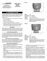
Little Giant TP 553674 Manual

Little Giant Pumpe TP 553674

Læs gratis den danske manual til Little Giant TP 553674 (8 sider) i kategorien Pumpe. Denne vejledning er vurderet som hjælpsom af 3 personer og har en gennemsnitlig bedømmelse på 5.0 stjerner ud af 2 anmeldelser. Har du et spørgsmål om Little Giant TP 553674, eller vil du spørge andre brugere om produktet?

Side 1/8
1

Modelos

ENGLISH
EN
This instruction sheet provides you with the information required to safely own
and operate your product. Retain these instructions for future reference.
The product you have purchased is of the highest quality workmanship and
material, and has been engineered to give you long and reliable service. This
delivery and operation. Please examine your item(s) carefully to ensure that no
damage occurred during shipment. If damage has occurred, please contact the
place of purchase. They will assist you in replacement or repair, if required.
      

     
       
        


We, Franklin Electric, declare that our pumps TPR, TPT & TPS with pump type
and serial number as shown on the nameplate are constructed in accordance
with Directives 2006/95/EC and 89/336/EEC and assume full responsibility for
conformity with the standards laid down therein.

Your Little Giant peristaltic condensate pump is designed as a fully automatic
condensate removal system for the water dripping off an air conditioner
evaporator coil. The pump is not for contiuous use applications. The pump you
have purchased is a small but powerful drain pump for the positive displacement
of condensate from fan coils and air conditioners. The design of this pump allows
the air handler to be located away from gravity water drains since the condensate
can be pumped to a common drain a distance away. The peristaltic pump is
designed to remove condensation from fan coil, wall-mount, ceiling and cassette
air conditioning equipment.



1. This pump is not to be used to pump flammable or explosive fluids such
as gasoline, fuel oil, kerosene, etc. Do not use this pump in explosive
atmospheres.
2. Do not handle pump with wet hands or when standing on a wet, damp
surface or when standing in water.
3. In any installation where property damage and/or personal injury might result
from an inoperative or leaking pump due to power outages, discharge line
blockage, or any other reason, a backup system(s) and/or alarm should be
used.
4. Support pump and piping when assembling and when installed. Failure to
do so may cause piping to break, pump to fail, motor bearing failures, etc; or
may cause the pump to malfunction.
5. Place pump in an area where there is no danger of ingress of water.

Maximum suction head: 2m (6.5 ft)
Maximum delivery head: 14m (49 ft)
Maximum ambient temperature: 50°C (122°)

1. Check the pump label for proper voltage and frequency required. Do not
connect to voltage and frequency other than that shown.
2. It is recommended to use ¼” I.D. or 6 mm I.D. tubing for both the inlet and
outlet. Inlet tubing is connected to the inlet fitting identified by an upward
arrow. Outlet or discharge tubing is connected to the outlet fitting identified
by a downward arrow.
3. Make sure the transparent cover is closed before operating.


The pump can be mounted adjacent, below or above (but not more than 2m
above) the condensate water source.
For best results, mount the pump with the hose connections facing down as
shown in Figure 1B.
A B C D

The pump may also be positioned on any side, but not placed rotor downward
(Figure 1C) or upward (Figure 1A). Connect 6.0mm or 1/4” tubing (not provided)
to the pump intake indicated by the arrow pointing upward on the transparent
cover. Position the other end of the intake tube in the drip tray drain hose and
seal it accordingly or place the intake tube in the drip tray (Figure 2). Be careful
not to twist, kink, or collapse the tubing. Run a length of 6.0mm or ¼” tubing (not
provided) from the discharge of the pump to a gravity drain. Refer to Figure 2 for
maximum vertical and horizontal discharge capabilities.
"Y r v r"
TPT
16 ft (5 m)
max
98 ft (30 m)
max
46 ft (14 m)
max
Lt. blue
Brown
Alternative position for inlet tube
To pump
Internal
drain tray
Inlet tube fixed
inside tray
outlet with
sealant
Ceiling
Red end: room air
sensor, intake air
Blue end: cold air
sensor, intake air
Coil
Block off unit drain
Internal drain tray
Wall or below ceiling A/C unit
6.5 ft (2 m) max

Be certain that there are no sharp bends or kinks in the suction and
discharge tubing. Keep all tubing and cables clear of moving parts in the air
handler. If using Ty-raps to secure tubing, be certain the Ty-rap does not collapse
tubing.

Locate the float reservoir in a suitable position below the bottom level of the drip
tray of the air conditioner. Be certain that the reservoir is within (+/-) 15 degrees
of being level. Optimum performance is achieved when the reservoir is level. If the
reservoir is not mounted properly, the float mechanism may not function properly
and may overflow.
Attach the 13mm (1/2”) tube (provided) to the reservoir intake and the drip tray
outlet or drain hose. Be certain to support the reservoir when attaching tubing
and make sure the tubing is not twisted, kinked or collapsed when reservoir is
in place. Connect the long 4 x 6 mm (5/32”) tubing (provided)to the discharge
of the reservoir marked “PUMP”. Connect the other end of the 4 x 6 mm (5/32”)
tubing to the provided 4 x 6 mm adapter. Use a short piece of 6 mm or ¼” tubing
(not provided) to connect the 4 x 6 mm adapter to the pump inlet fitting identified
by an upward arrow. Connect the short 4 x 6 mm (5/32”) tubing (provided) to
the outlet of the reservoir marked “VENT”. The free end of the tubing must be
directed upward above the drip tray to prevent overflow. Be certain the tubing is
not twisted, kinked or collapsed when installed.

SHUT OFF ELECTRICAL POWER AT FUSE BOX BEFORE MAKING ANY
CONNECTIONS. ALL WIRING MUST COMPLY WITH LOCAL CODES. CHECK
THE PUMP LABEL FOR PROPER VOLTAGE REQUIRED. DO NOT CONNECT TO
VOLTAGE OTHER THAN THAT SHOWN.
 (compressor or cooling signal) - Connect the brown wire to the main
phase (line), the blue wire to the neutral phase (common). The pump must not
be connected to a switched line. Electricity should always be provided on this
line. Connect the orange wire to the compressor or cooling signal (Figure 3).
When the compressor engages, a 230V supply voltage will be sent to start the
pump. When the compressor stops operating, the pump will not stop. The pump
is programmed to continue operating for another 5 minutes to collect any residual
condensate before stopping.
: The compressor or cooling signal neutral phase (common) needs to be
the same neutral phase (common) that is used to supply power to the controller.
  (temperature signal) FOR PROPER PUMP OPERATION, PLEASE
FOLLOW THESE INSTRUCTIONS: Connect the brown wire to the main phase
(line) and the blue wire to the neutral phase (common) (Figure 2). Make sure
power is off when connecting the temperature sensor to the pump. Connect the
sensor cable to the pump by connecting the 4-prong plug to the corresponding

Oklahoma City, OK
www.LittleGiantPump.com
customerservice@lgpc.com
2
cable on the pump. There are 2 lead wires with sensors at the ends; one lead has
a blue end and the other has a a red end. Affix the wire with the blue sensor to
the “cold” or “air out” side of the evaporator coil and the wire with the red sensor
to the “hot” or “air in” side of the evaporator coil (Figure 2).

The pump will start when a temperature difference of 5°C (9°F) is reached between
the blue and red sensor. As long as the difference in temperature is more than
5°C (9°F), the pump will operate. When the difference in temperature is less than
5°C (9°F), the current cuts off and the pump will continue to operate for 5 minutes
then stop. Never put the sensors directly into water or condensate. Do not 
attach the sensors to the refrigeration piping. Do not leave the sensors loose in
the open air.
 (reservoir control tank) - Connect the brown wire to the main phase
(line) and the blue wire to the neutral phase (common) (Figure 4). Make sure
power is off when connecting the reservoir to the pump. Connect the cable
corresponding cable on the pump.

    - Connect the cables as described
below to obtain the desired response:
 When water rises, the circuit opens to turn off the compressor and
prevents overflow by connecting the gray with the blue stripe wire and the yellow
with the blue stripe wire. (Figure 4)
 When water rises, the circuit closes to activate a bell or alarm (not
provided) by connecting the gray with the blue stripe wire and the purple with the
yellow stripe wire (Figure 4).
The rating for the alarm circuit is 200VDC, 1 amp max., and 15 watts max.

Brown – main phase (line)
Blue – neutral phase (common)
After electrical connections have been made, check the pump for proper
operation. Press the test switch to determine if pump operates properly.

DISCONNECT THE PUMP FROM THE POWER SOURCE BEFORE SERVICING
OR REMOVING ANY COMPONENTS.


: Carefully remove the reservoir cover by gently flexing the locking tab.
Be careful not to damage the o-ring. Remove the mesh screen and rinse it under
running water. Remove any debris that may block the mesh. Use a damp cloth to
remove dust or debris from the reservoir. When re-installing the float/magnet, be
certain that the beveled edge of the float is up and the magnet is properly seated
before reassembling the reservoir. Carefully hook the cover and then press it onto
the tank until the spring tab snaps in place. Use care to make sure the o-ring is
properly installed (that is, not twisted, torn, or otherwise out of its track.)
599270 T-RPC REPLACEMENT TUBE ASSY
PUMP WIRING CONFIGURATION
WILL BE DIFFERENT DEPENDING
ON WHICH MODEL WAS PURCHASED
PART NO. DESCRIPTION
944322
153781
951584
TPR
TPR
TPT
TEMPERATURE SENSOR CABLE ASSY
REPLACEMENT PARTS NOT SHOWN
TUBE, NATURAL RUBBER
RESERVOIR ASSEMBLY
USED ON MODEL


1. Disconnect the pump from the power source.
2. Open the transparent cover.
3. To remove the pump tube, put the rotor in a vertical position, and remove
the inlet side tubing from its left seat. Pull the tubing upward while manually
rotating the rotor clockwise. Fully remove the tube from the right seat.
4. Apply a small amount of silicone grease to the new tube before installing it;
this will help lubricate the tube. No other lubrication is required.
5. To install the pump tube, put the rotor in a horizontal position. Push the inlet
side tube connector into the left seat, making sure it is fully inserted. While
rotating the rotor clockwise, push the tubing into place. Once the tubing is
moved into position, insert the outlet connector into the seat of the right side.
6. Close the transparent front cover.

Dispose of or recycle product properly, according to all relevant authorities.
FRANÇAIS
FR
Cette feuille d’instructions vous fournit les informations cessaires pour
entretenir et faire fonctionner votre produit. Conserver ces directives afin de
pouvoir les consulter plus tard.
Le produit que vous avez acheté a ésoigneusement fabriqavec des matériaux
de la plus haute qualiet a été conçu pour durer longtemps et offrir un service
fiable. Les produits sont soigneusement testés, inspectés et emballés afin d’en
assurer la curité de fonctionnement et une livraison en bonne condition. Vérifier
attentivement le produit afin de vous assurer qu’il n’a pas été endommagé pendant
le transport. S’il est endommagé, veuillez contacter l’entreprise qui vous l’a vendu.
Si une réparation ou un remplacement est requis, elle vous prêtera assistance.
       
   






Nous, Franklin Electric déclarons que les pompes TPR, TPT, TPS modèle
et numero de série marqués sur la plaque signalétique sont conformes aux
Directives 2006/95/EC, 89/336/EEC.

Votre pompe péristaltique à condensat Little Giant est conçue comme un
système de purgeur entièrement automatique de condensat pour l’eau qui
s’égoutte du serpentin d’évaporation d’un conditionneur d’air. Ne pas utiliser
la pompe avec des applications qui fonctionnent continuellement. La pompe
que vous avez achetée est une pompe d’évacuation compacte et efficace pour
l’enlèvement du condensat provenant des serpentins et des conditionneurs d’air.
La conception de cette pompe permet que la section de traitement d’air soit
éloignée des purges d’eau, puisque le condensat peut être pompé vers un drain
commun situé à une certaine distance. La pompe péristaltique est conçue pour
enlever la condensation d’un montage mural, de l’équipement de plafond et de
cassette d’un conditionneur d’air et d’un serpentin.
TPs



Produkt Specifikationer

Mærke: Little Giant
Kategori: Pumpe
Model: TP 553674

Har du brug for hjælp?

Hvis du har brug for hjælp til Little Giant TP 553674 stil et spørgsmål nedenfor, og andre brugere vil svare dig