Manfrotto MSTANDVR Manual
Manfrotto
Ikke kategoriseret
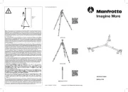
MSTANDVR

| Mærke: | Manfrotto |
| Kategori: | Ikke kategoriseret |
| Model: | MSTANDVR |
| Vægt: | 1150 g |
| Produktfarve: | Sort |
| Materiale: | Aluminium |
| Styrehjul: | Ingen |
| Formål: | Belysningssystem |
| Hældningsvinkelområde: | - ° |
| Antal ben: | 3 ben |
| Højde (min.): | 720 mm |
| Højde (maks.): | 2120 mm |
| Maksimal vægtkapacitet: | 0.5 kg |
| Drejevinkel: | - ° |
| Fodaftryk diameter (maks.): | 1090 mm |
| Pladebredde: | - mm |
| Pladedybde: | - mm |
| Stativ gevind: | 1/4, 3/8, 5/8 " |
| Foldet længde: | 860 mm |
| Antal benafsnit: | 4 |
Har du brug for hjælp?
Hvis du har brug for hjælp til Manfrotto MSTANDVR stil et spørgsmål nedenfor, og andre brugere vil svare dig
Ikke kategoriseret Manfrotto Manualer
15 Oktober 2025

2 Oktober 2025
14 Juli 2025
9 Juli 2025
8 Juli 2025
8 Juli 2025

8 Juli 2025

27 Marts 2025

23 December 2024

21 December 2024
Ikke kategoriseret Manualer
- Syma
- Desview
- Wegman
- ESKA
- Devolo
- Evooch
- Thermalright
- Fiilex
- Kenmore
- BOHLT
- 9.solutions
- Rosieres
- Hard Head
- Scosche
- VAVA
Nyeste Ikke kategoriseret Manualer

4 November 2025
4 November 2025
4 November 2025

4 November 2025
4 November 2025

4 November 2025
4 November 2025

4 November 2025

4 November 2025

4 November 2025