PLEASE REFER TO THE HIGHWAY CODE REGARDING
Please check all screws and are secure before giving to your child.
MV recommends the use of protective pads bicycle and helmet
1. Push the saddle pillar into the down tube at
least as far as the Minimum insertion mark.
2. Align the saddle with the bike frame and
* Under no circumstances should the seat
post project from the frame beyond its
Minimum Insertion mark. If your seat post
projects from the frame beyond these markings,
the seat post or frame may break, which could
cause you to lose control and fall.
(NOTE: illustration may differ to actual bike.)
NOTE: Line up the pedal carefully with the hole in the wheel crank ensuring that
it does not become cross threaded
Please retain this for reference to the manufacturer.
Made in t Phillippines to European Safety Standards.he
35 Tameside Drive Castle Bromwich Birmingham B35 7AG UK• • • •
PLEASE READ BEFORE ASSEMBLY
1. Frame Assembly (shape may dier)
4. Handlebars (shape may dier)
9. Plastic basket (optional)*
Impor t o r’s informationtan wne
Plea rea thi befor allowin you chil idse d s e g r d to r e the bicycle.
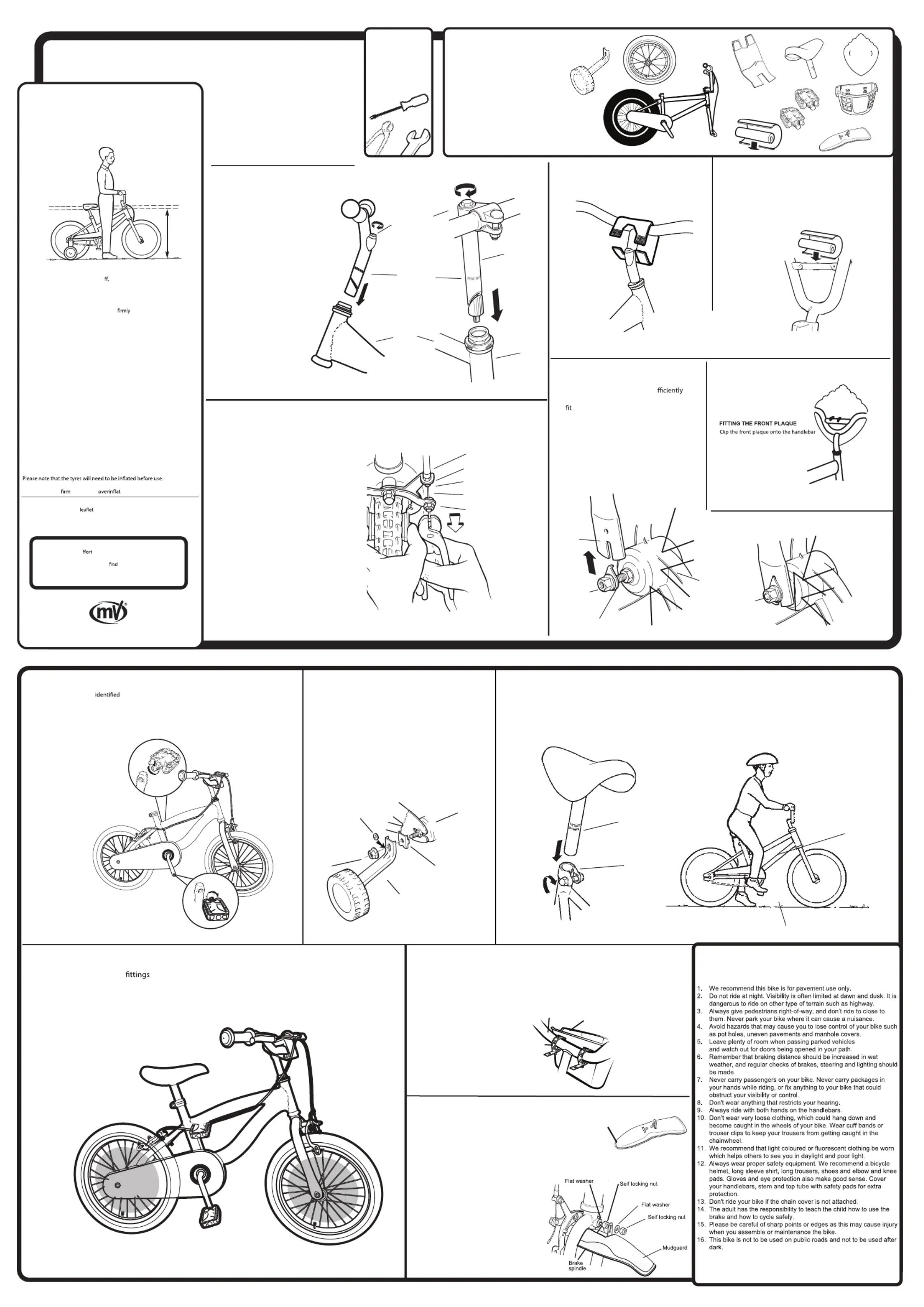
M e sure e b le you h e t is the c rect size r the child.ak th icyc av bough or fo
The rider’s crotch should be 25mm higher than the top tube of the bicycle.
It is e en l that, ore moving oss tia bef
the ri r is t ly edde comfor ab seat
on e bi le and not st t ing r d to ach e d rs.th cyc re ch fo war re th han leba
R eck the i t ons n r the ins llation of e le.e-ch ns ructi give fo ta th sadd
FO YO IL FETR UR CH D A’S S Y
R heck t l sc s, nuts and bolts are t tened.ec tha al rew igh
Make sure that your ild is le of ri g t s cycle.ch capab din hi bi
Do t a ow y r child to ride with t sion.no ll ou ou supervi
C inha shoul had ve a atel m tical ntpproxim y 10m of ver moveme
wh cken che ed i t t t r tn he cen re be ween the f on an r .d rear sp ocket
T adjo ust t ha tension n o a h l r n utshe c in , loose tw re r w ee etai ing n
and th move e rea x r rds or a le e her foit wa r b o adjus e tensackwards t t h t ion.
R t h uts o orr t tensi i i d.e- ig ten n nce c ec on s ach eve
B ke b cks must be ked by an ult at u r . It isra lo chec ad reg la intervals
recommen bra blocded that the ke ks are ced if y come ssrepla the be le
s with l ht ma ine oil at r s orig ch regula interval
R O D TEC MMENDE OR OLERANCQUE T ES (Nm - Newton Meter)
Tyre pres re sisu 35psi - 40 p
1. Loosen the front wheel nuts su
to allow the tabbed locating washers to
2. Insert the front wheel into the front forks,
sliding the wheel spindle into the slots in
3. Ensure that the locating washer tabs are
inserted into the holes in the fork end.
4. Check that the wheel rim is central between
the forks and tighten the wheel nuts.
We make every e to ensure that this product reaches
you in satisfactory condition. However if you have any
queries, need assistance, or
please contact our Customer Services:
customer.services@mvsports.com. Alternatively, you can
Pl gin uneas kee ackae p the p g til you have
com ly ed the le.plete assembl bicyc
Thi bi bl dus cyc assemle is to be ed by an a lt
Ch k the c nts and y ove theec onte onl rem
pro ive p g om h i m as andtect ackagin fr eac te
when it is to be fi ed.tt
Permissible total weight of the rider plus
luggage should be 40kg and the maximum
total weight should be 50kg.
Any and ar wear te on y n rak t res, tubes a d b e f s musriction-component t e b
ch cke ed y a u P s o l b n ad lt. lea e n te he pl e umbe r epin n r o f r l aacement p rts.
Only use genuine replecement parts for safety-critical components.
2. On the brake arm, loosen the anchor nut and bolt.
1. Ensure the brake callipers are secure to the frame.
3. Squeeze the brake shoes together and using a pair of
pliers, pull the inner brake cable tight.
4. Re-tighten the cable anchor nut and bolt.
5. Using the cable adjuster, adjust the brakes to give 1.5mm
clearance between the brake blocks and the wheel rim
6. Tighten the cable adjuster lock nut.
7. Check that the brake blocks make contact with the
wheel rim and not the tyre.
NOTE: Please ensure the brake levers do not swivel on the handlebar tube.
Position levers once handlebar is fixed and tighten.
16’’ Generic Bike / Boy and Girl
FITTING A STEM PAD (optional)
1. If your bike includes a stem pad wrap it around
the handlebars and secure.
NOTE: The left hand brake lever operates the rear brake and the right hand brake lever operates the front brake.
Handlebar Expander Bolt 15-17 Nm
Handlebar Clamp Bolt 16-18 Nm
ATTACHING A CRASHPAD (optional)
If your bike includes a crash pad wrap
the foam tube around the cross bar.
Handlebar design will change depending
(NOTE: depending on bike style.)
ATTACHING THE BASKET (optional)
FITTING THE MUDGUARD (optional)
Basket
Handlebars
Strap
(NOTE: depending on bike style.)
(NOTE: depending on bike style.)
(NOTE: depending on bike style.)
W st t srap raps around handlebar en ering strap end
in one he available shaped hole onto of t ‘T’ s the
pro ruding piece rap undernea ecurt o stf th o t s e
t .he baske int place
1. Remove the first self locking nut and flat washer
2. Fit the front mudguard support bracket onto
3. Refit the flat washer and self locking nut and
NOTE: Please check the brake assembly
operates correctly after re-assembly
(NOTE: illustrations may difer to actual bike/depending
*Some models do not have optional component.
*Some models do not have this optional component.
*Some models do not have this optional component.
(NOTE: depending on bike style.)
*Some models do not have this optional component.
*Some models do not have this optional component.
*Some models do not have this optional component.
FITTING THE STABILISERS (optional)
1. Remove the nut and washer from the rear axle frame assembly
leaving the stabiliser frame bracket in position.
2. Slide the stabiliser over the threaded axle spindle end.
3. Replace nut and washer and tighten.
4. To adjust the stabiliser wheel height, loosen the nut, slide
the stabiliser up or down to adjust the wheel height and
* It is very important to check the stabiliser
connection to the bicycle. Failure to properly
tighten may cause the stabilser to dislodge.
Pay attention for risk when using stabiliser.
When the stabilisers are removed please be
sure to replace the bracket and nut to cover
NOTE: The pedals are as right
hand or left hand by an 'R' or 'L' on the
1. Screw the pedal marked 'R' clockwise
into the right hand chain wheel crank
(side with chainguard) and tighten
2. Screw the pedal marked 'L'
anti-clockwise into left hand
crank and tighten securely.
11. Stabiliser arm and wheel p1-x2 (optional)*
12. Front Plaque (optional)*
ATTACHING THE PLAQUE (optional)


