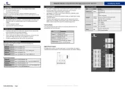
Microchip TC4426A Manual


Læs gratis den danske manual til Microchip TC4426A (10 sider) i kategorien Ikke kategoriseret. Denne vejledning er vurderet som hjælpsom af 22 personer og har en gennemsnitlig bedømmelse på 5.0 stjerner ud af 11.5 anmeldelser. Har du et spørgsmål om Microchip TC4426A, eller vil du spørge andre brugere om produktet?

Side 1/10
2004 Microchip Technology Inc. DS00799B-page 1
AN799
INTRODUCTION
There are many MOSFET technologies and silicon
processes in existence today, with new advances being
made every day. To make a generalized statement
about matching a MOSFET driver to a MOSFET based
on voltage/current ratings or die sizes is very difficult, if
not impossible.
As with any design decision, there are multiple vari-
ables involved when selecting the proper MOSFET
driver for the MOSFET being used in your design.
Parameters such as input-to-output propagation delay,
quiescent current, latch-up immunity and driver current
rating must all be taken into account. Power dissipation
of the driver will also effect your packaging decision
and driver selection.
This Application Note discusses the details of MOSFET
driver power dissipation in relation to MOSFET gate
charge and operating frequency. It also discusses how
to match MOSFET driver current drive capability and
MOSFET gate charge based on desired turn-on and
turn-off times of the MOSFET.
Microchip offers many variations of MOSFET drivers in
various packages, which allows the designer to select
the optimal MOSFET driver for the MOSFET(s) being
used in their application.
POWER DISSIPATION IN A MOSFET
DRIVER
Charging and discharging the gate of a MOSFET
requires the same amount of energy, regardless of how
fast or slow (rise and fall of gate voltage) it occurs.
Therefore, the current drive capability of the MOSFET
driver does not effect the power dissipation in the driver
due to the capacitive load of the MOSFET gate.
There are three elements of power dissipation in a
MOSFET driver:
1. Power dissipation due to the charging and
discharging of the gate capacitance of the
MOSFET.
EQUATION 1:
2. Power dissipation due to quiescent current draw
of the MOSFET driver.
EQUATION 2:
3. Power dissipation due to cross-conduction
(shoot-through) current in the MOSFET driver.
EQUATION 3:
As deduced from the equations above, only one of the
three elements of power dissipation is due to the
charging and discharging of the MOSFET gate
capacitance. This portion of the power dissipation is
typically the highest, especially at lower switching
frequencies.
In order to calculate a value for Equation 1, the gate
capacitance of the MOSFET is required. The gate
capacitance of a MOSFET is comprised of two capaci-
tances: the gate-to-source capacitance and the gate-
to-drain capacitance (Miller Capacitance). A common
mistake is to use the Input Capacitance rating of the
MOSFET (CISS) as the total gate capacitance of the
MOSFET. The proper method for determining gate
capacitance is to look at the Total Gate Charge (QG) in
the MOSFET data sheet. This information is typically
shown in the Electrical Characteristics table and as a
typical characteristics curve in any MOSFET data
sheet.
Author: Jamie Dunn
Microchip Technology Inc.
PCCGVDD
2F××=
Where:
CG= MOSFET Gate Capacitance
VDD = Supply Voltage of MOSFET Driver (V)
F = Switching Frequency
PQIQH D IQL 1 D( )×+×( ) VDD
×=
Where:
IQH = Quiescent current of the driver with
the input in the high state
D = Duty cycle of the switching waveform
IQL = Quiescent current of the driver with
the input in the low state
PSCC F VDD
××=
Where:
CC = Crossover constant (A*sec)
Matching MOSFET Drivers to MOSFETs
AN799
DS00799B-page 2 2004 Microchip Technology Inc.
Table 1 shows a typical example of the data sheet
representation of gate charge for a 500V, 14A, N-chan-
nel MOSFET. Note that the values given in the data
sheet table have conditions associated with them: gate
voltage and drain voltage. These conditions effect the
gate charge value. Figure 1 shows the gate charge typ-
ical characteristic curve for the same MOSFET as it
varies with gate voltage and drain voltage. Make sure
the gate charge value you use for calculating power
dissipation fits the conditions of your application.
Taking a typical value from the graph in Figure 1 for
VGS = 10V, we get a total gate charge of 98 nC
(VDS = 400V). Using the relationship Q = C * V, we get
a gate capacitance value of 9.8 nF, which is signifi-
cantly higher than the 2.6 nF input capacitance that is
specified in Table 1. This illustrates the fact that when
a calculation calls for a gate capacitance value, the
total gate capacitance value should be derived from the
total gate charge value.
FIGURE 1: Total Gate Charge vs. Gate-
to-Source Voltage (500V, 14A, N-channel
MOSFET).
When using maximum values for gate charge from the
Electrical Characteristics table for worst-case design,
the values must be adjusted for the drain-to-source and
gate-to-source voltages in your design.
Using the MOSFET information presented in Table 1
and Figure 1 as an example, the power dissipation in a
MOSFET driver due to the charging and discharging of
the gate capacitance of this MOSFET with a V
GS of
12V, a switching frequency of F = 250 kHz and a drain-
to-source voltage of 400V would be:
The value for CG is arrived at by using the graph in
Figure 1 and finding the value for QG at 12V. QG is then
divided by 12V to get the C
G value. Knowing that QG is
equal to CG * VG
, the equation for PC could be rewritten
as:
A note of importance is that the voltage in this equation
is squared. Therefore, a reduction in the gate drive
voltage can result in a significant reduction in power
loss in the driver. For some MOSFETs, driving the gate
voltage above 8V to 10V does not result in any further
decrease in MOSFET resistance (RDS-ON). Using the
same MOSFET as above as an example, a 10V gate
drive results in the following power dissipation:
The 16% reduction in gate voltage (going from 12V to
10V) resulted in a 28% reduction in power dissipation
due to gate drive. Further savings will also be seen in
the cross-conduction losses due to gate drive voltage
reduction.
Equation 3 represents the power dissipation due to
MOSFET driver cross-conduction, or what is
commonly referred to as shoot-through. This is a result
of the P-channel and N-channel FETs in the output
drive stage being on at the same time as they
transition between the on and off states.
TABLE 1: DATA SHEET REPRESENTATION FOR GATE CHARGE
Pin
Name Parameter Min. Typ. Max. Units Test Conditions
QGTotal Gate Charge 150
nC
ID = 14A
VDS = 400V
VGS = 10V
QGS Gate-to-Source Charge 20
QGD Gate-to-Drain Charge 80
CISS Input Capacitance 2600
pF
VGS = 0V
VDS = 25V
f = 1.0 MHz
COSS Output Capacitance 720
CRSS Reverse Transfer Capacitance 340
0
2
4
6
8
10
12
14
16
18
20
0
10
20
30
40
50
60
70
80
90
100
110
120
130
140
QG, Total Gate Charge (nC)
VGS , Gate-to-Source Voltage (V)
VDS = 400V
VDS = 250V
VDS = 100V
PCCGV2F××=
PC9.5 10 9
×12( )2250 103
×××=
PC342mW=
PCQGV×F×=
PCQGV×F×=
PC98 10 9
×10×250 103
××=
PC245mW=


Produkt Specifikationer

Mærke: Microchip
Kategori: Ikke kategoriseret
Model: TC4426A

Har du brug for hjælp?

Hvis du har brug for hjælp til Microchip TC4426A stil et spørgsmål nedenfor, og andre brugere vil svare dig