Monacor TXA-1020MR Manual

Monacor Radio TXA-1020MR

Læs gratis den danske manual til Monacor TXA-1020MR (6 sider) i kategorien Radio. Denne vejledning er vurderet som hjælpsom af 23 personer og har en gennemsnitlig bedømmelse på 4.5 stjerner ud af 12 anmeldelser. Har du et spørgsmål om Monacor TXA-1020MR, eller vil du spørge andre brugere om produktet?

Side 1/6
®
MONACOR INTERNATIONAL GmbH & Co. KG • Zum Falsch 36 28307 Bremen Germany Copyright
©by MONACOR INTERNATIONAL. All rights reserved. A-1628.99.02.06.2018
ELECTRONICS FOR SPECIALISTS ELECTRONICS FOR SPECIALISTS ELECTRONICS FOR SPECIALISTS ELECTRONICS FOR SPECIALISTS ELECTRONICS FOR SPECIALISTS ELECTRONICS FOR SPECIALISTS ELECTRONICS FOR SPECIALISTS ELECTRONICS FOR SPECIALISTS ELECTRONICS FOR SPECIALISTS ELECTRONICS FOR SPECIALISTS ELECTRONICS FOR SPECIALISTS
2-Channel Receiver Module
These instructions are intended for experts (installation) and
for users without any technical knowledge (operation).
Please read these instructions carefully prior to installation/
operation and keep them for later reference.
1 Applications
In combination with two appropriate transmitters (e. g. TXA-
800HSE, TXA-800HT), this 2-channel receiver module is used to
establish two wireless audio transmission paths. The module is
especially designed for installation into an active speaker system
of the series TXA-1020 or TXA-800 (for replacing a receiver mod-
ule or for retrofitting) but may also be installed into other units.
Conformity and approval:
Herewith, MONACOR INTERNATIONAL declare that the re ceiv er
module TXA-1020MR complies with the directive 2014/53/ EU.
The EU declaration of conformity is available on the Internet:
www.monacor.com
The receiver module and the corresponding transmitters are gen-
erally approved for operation in EU and EFTA countries; they are
licence-free and require no registration.
2 Important Notes
The module corresponds to all relevant directives of the EU and
is therefore marked with .
GThe module is suitable for indoor use only. Protect it against
dripping water and splash water, high air humidity and heat
(admissible ambient temperature range 0 40 °C).
GFor cleaning the front, only use a dry, soft cloth; never use water
or chemicals.
GNo guarantee claims for the module and no liability for any
resulting personal damage or material damage will be accepted
if the module is used for other purposes than originally
intended, if it is not correctly installed or operated, or if it is not
repaired in an expert way.
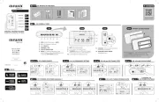
3 Installation
Installation into an active speaker system of the series
TXA-1020 /-800:
1) To install the module as an additional receiver module, screw
off the cover of the unused insertion compartment to the right
of the receiver module already installed.
To replace a receiver module already installed, screw the
module off and remove it from its compartment.
2) Insert the module TXA-1020MR into the compartment and
screw its front plate to the unit. Make sure to correctly insert
the printed circuit board into the lateral guide rails of the com-
partment.
The unit into which the module is to be inserted must be
switched off and disconnected from the mains!
If the module is to be put out of operation definitively,
take it to a local recycling plant for a disposal which is
not harmful to the environment.
Deutsch
TXA-1020MR
Bestell-Nr. • Order No. 17.4630
Installation into another unit:
Make sure to observe the CE directives. Estab-
lish the connection via the contacts of the
printed circuit board:
4 Operation (also see separate sheet: “Settings”)
Each receiver unit (A and B) provides a control to adjust the vol-
ume and to switch it on and off. The display is divided into two
parts: left half for receiver unit A, right half for receiver unit B.
When a receiver unit has been switched on, the display will indi-
cate the transmission channel. To briefly indicate the radio fre-
quency, press the button (for unit A) or (for unit B). 
Establishing wireless transmission paths
1) Use the controls to switch on the receiver units and then
set the transmission channels manually or via channel scan
(separate sheet: “Settings”). Do not switch on the two cor-
responding transmitters for the time being.
If, with the transmitter switched off, the respective segment
bar A or B on the display indicates reception, interference sig-
nals or signals from other transmitters are being received. In
this case, select a different channel.
2) Switch the transmitters on and set them to the channel of
receiver unit A and receiver unit B respectively. The respective
segment bars on the display will then indicate the strength of
the radio signals received. Use the controls to adjust the
desired volume for each receiver unit.
If no reception is indicated or if the reception is poor, check if:
– the batteries of the transmitter are discharged
– the reception is disturbed by metal objects or other high-fre-
quency sources
– the distance (transmitter receiver module) is too long
– the squelch value is too high (separate sheet)
Note concerning operation with two 2-channel receiver modules:
When using the channel scan, change the group setting for both
receiver modules (separate sheet).
5 Specifications
Transmission range: . . . . . . approx. 30 m
Power supply: . . . . . . . . . . .
12 V/ 150 mA
Dimensions, weight: . . . . . . 88 × 37 × 135 mm (W × H × D), 98 g
Subject to technical modification.
Radio frequencies in MHz (2 × 16 channels)
01 02 03 04 05 06 07 08
863.1 864.1 863.6 864.6 863.3 864.3 863.8 864.8
09 10 12 13 14 15 1611
863.2 864.2 863.7 864.7 863.4 864.4 863.9 864.9
Pin configuration
1 Antenna input, channel A
2 Ground
3 Operating voltage +12 V
4 Ground
5 Audio output (line level)
6 Ground
7 Not required
8If required: for an LED (with anode at +12 V) to
indicate reception
9 Ground
10 Antenna input, channel B
2-Kanal-Empfangsmodul
Diese Anleitung richtet sich sowohl an Fachleute (Einbau)
als auch an Personen ohne technisches Fachwissen (Be -
die nung). Bitte lesen Sie die Anleitung vor dem Betrieb
gründlich durch und heben Sie sie für ein späteres Nachle-
sen auf.
1 Verwendungsmöglichkeiten
Dieses 2-Kanal-Empfangsmodul dient, in Verbindung mit zwei
passenden Sendern (z. B. TXA-800HSE, TXA-800HT), zum Auf-
bau von zwei drahtlosen Audio-Übertragungsstrecken. Das
Modul ist speziell für den Einbau in eine Ak tivbox der Serie
TXA-1020 oder TXA-800 konzipiert (zum Austausch eines Emp-
fangsmoduls oder zur Nachrüstung), lässt sich jedoch auch in ein
anderes Gerät einbauen.
Konformität und Zulassung:
Hiermit erklärt MONACOR INTERNATIONAL, dass das Emp-
fangsmodul TXA-1020MR der Richtlinie 2014/53/ EU entspricht.
Die EU-Konformitäts erkrung ist im Internet verfügbar:
www.monacor.de
Das Empfangsmodul und die zugehörigen Sender sind r den
Be trieb in den EU- und EFTA-Staaten allgemein zugelassen und
anmelde- und ge bührenfrei.
2 Wichtige Hinweise
Das Modul entspricht allen relevanten Richtlinien der EU und ist
deshalb mit gekennzeichnet.
GDas Modul ist nur zur Verwendung im Innenbereich geeignet.
Schützen Sie es vor Tropf- und Spritzwasser, hoher Luft -
feuchtigkeit und Hitze (zulässiger Einsatztemperaturbereich
0 – 40 °C).
GVerwenden Sie zum Reinigen der Front nur ein trockenes, wei-
ches Tuch, auf keinen Fall Wasser oder Chemikalien.
GWird das Modul zweckentfremdet, nicht fachgerecht eingebaut,
falsch bedient oder nicht fachgerecht repariert kann keine Haf-
tung für daraus resultierende Sach- oder Personenschäden
und keine Garantie für das Modul übernommen werden.
3 Einbau
Einbau in eine Aktivbox der Serie TXA-1020/-800:
1) Soll das Modul als zusätzliches Empfangsmodul eingebaut
werden, die Blende des freien Einschubschachts rechts neben
dem eingebauten Empfangsmodul abschrauben.
Soll das Modul ein eingebautes Empfangsmodul ersetzen,
dieses abschrauben und aus dem Schacht ziehen.
2) Das Modul TXA-1020MR in den Schacht schieben und mit der
Frontplatte am Gerät festschrauben. Beim Hineinschieben
darauf achten, die Leiterplatte in die seitlichen Führungsschie-
nen des Schachts zu stecken.
Das Gerät, in welches das Modul eingebaut werden soll, muss
unbedingt ausgeschaltet und von der Netzspannung getrennt
werden!
Soll das Modul endgültig aus dem Betrieb ge nom men
werden, übergeben Sie es zur umwelt gerechten Ent-
sorgung einem örtlichen Recyclingbetrieb.
Einbau in ein anderes Gerät:
Die CE-Richtlinien müssen be achtet werden.
Den An schluss über die Leiterbahnkontakte her -
stellen:
4 Bedienung (siehe auch Extrablatt: „Einstellungen“)
Die Empfangseinheiten A und B haben jeweils einen Regler zum
Einstellen der Lautstärke und zum Ein-/Ausschalten. Das Display
ist aufgeteilt für Empfangseinheit A (linke Hälfte) und Empfangs-
einheit B (rechte Hälfte). Nach dem Einschalten einer Empfangs-
einheit zeigt das Display den Übertragungskanal. Zum kurzen
Anzeigen der Funkfrequenz die Taste (für Einheit A) oder  
(für Einheit B) drücken.
Funkstrecken aufbauen
1) Die Empfangseinheiten mit den Reglern einschalten und die
Übertragungskanäle über den Kanalsuchlauf oder manuell
einstellen (Extrablatt: „Einstellungen). Die zwei zugehöri-
gen Sender dabei vorerst noch ausgeschaltet lassen.
Zeigt im Display die jeweilige Segmentanzeige A oder B
bei ausgeschaltetem Sender Empfang an, werden Störsignale
bzw. Signale an derer Sender empfangen. In diesem Fall einen
anderen Kanal auswählen.
2) Die Sender einschalten und jeweils auf den Kanal von Emp-
fangseinheit A und den Kanal von Empfangseinheit B einstel-
len. Im Display zeigen dann die jewei ligen Segmentanzeigen
die Stärke des Funkempfangs an. Mit den Reglern für jede
Empfangseinheit die Lautstärke ein stellen.
Wird kein Empfang angezeigt oder ist der Empfang schlecht,
überprüfen ob,
– die Batterien/Akkus des Senders verbraucht sind
– der Empfang durch Metallgegenstän de oder andere Hoch-
frequenz-Quellen gestört wird
– der Abstand Sender — Empfangsmodul zu groß ist
– der Squelch-Wert (Extrablatt) zu hoch ist
Hinweis zum Betrieb mit zwei 2-Kanal-Empfangsmodulen: Wird
der Kanalsuchlauf genutzt, für beide Empfangsmodule die Gruppen-
einstellung ändern (Extrablatt).
5 Technische Daten
Übertragungsreichweite: . . . ca. 30 m
Stromversorgung: . . . . . . . .
12 V/ 150 mA
Abmessungen, Gewicht: . . . 88 × 37 × 135 mm ( T), 98 gB × H ×
Änderungen vorbehalten.
Kontaktbelegung
1 Antenneneingang, Kanal A
2 Masse
3 Betriebsspannung +12 V
4 Masse
5 Audioausgang (Line-Pegel)
6 Masse
7 wird nicht benötigt
8bei Bedarf: für eine LED (mit der Anode an
+12 V) zur Empfangsanzeige
9 Masse
10 Antenneneingang, Kanal B
Funkfrequenzen in MHz (2 × 16 Kanäle)
01 02 03 04 05 06 07 08
863,1 864,1 863,6 864,6 863,3 864,3 863,8 864,8
09 10 12 13 14 15 1611
863,2 864,2 863,7 864,7 863,4 864,4 863,9 864,9
Deutsch
English
®
MONACOR INTERNATIONAL GmbH & Co. KG • Zum Falsch 36 28307 Bremen Germany Copyright
©by MONACOR INTERNATIONAL. All rights reserved. A-1628.99.02.06.2018
ELECTRONICS FOR SPECIALISTS ELECTRONICS FOR SPECIALISTS ELECTRONICS FOR SPECIALISTS ELECTRONICS FOR SPECIALISTS ELECTRONICS FOR SPECIALISTS ELECTRONICS FOR SPECIALISTS ELECTRONICS FOR SPECIALISTS ELECTRONICS FOR SPECIALISTS ELECTRONICS FOR SPECIALISTS ELECTRONICS FOR SPECIALISTS ELECTRONICS FOR SPECIALISTS
Modulo di ricezione a 2 canali
Queste istruzioni sono rivolte sia ad esperti (montaggio) che
a persone senza conoscenze tecniche specifiche (funziona-
mento). Vi preghiamo di leggerle attentamente prima della
messa in funzione e di conservarle per un uso futuro.
1 Possibilità d'impiego
Questo modulo di ricezione a 2 canali serve, insieme a due tra-
smettitori adatti (p. es. TXA-800HSE, TXA-800HT), per la crea-
zione di due sistemi wireless di trasmissione audio. Il modulo è
previsto in modo particolare per il montaggio in una cassa attiva
della serie TXA-1020 o TXA-800 (come montaggio successivo
oppure per sustituire un modulo di ricezione), ma p essere
montato anche in un altro apparecchio.
Conformità e omologazione:
La MONACOR INTERNATIONAL dichiara che il modulo di rice-
zione TXA-1020MR è conforme alla direttiva 2014 / 53 / UE. La
dichiarazione di conformità UE é disponibile in Internet:
www.monacor.com
Il modulo di ricezione e i relativi trasmettitori sono omologati per
l'impiego negli stati dellʼUE e dellʼEFTA e non richiedono
registrazione né pagamento di tasse.
2 Avvertenze importanti
Il modulo è conforme a tutte le direttive rilevanti dellʼUE e pertanto
porta la sigla .
GIl modulo è previsto solo per uso allʼinterno di locali. Proteg-
gerlo dall'acqua gocciolante e dagli spruzzi d'acqua, da alta
umidità dell'aria e dal calore (temperatura dʼimpiego ammessa
fra 0 e 40 °C).
GPer la pulizia del frontale usare solo un panno morbido,
asciutto; non impiegare in nessun caso acqua o prodotti chi-
mici.
GNel caso uso improprio, di montaggio non a regola dʼarte,
dʼimpiego scorretto o di riparazione non a regola arte del
modulo, non si assume nessuna responsabilità per eventuali
danni consequenziali a persone o a cose e non si assume nes-
suna garanzia per il modulo.
3 Montaggio
Montaggio in una cassa attiva della serie
TXA-1020 /-800
:
1) Se il modulo deve essere montato come modulo di ricezione
supplementare, svitare la mascherina del vano libero per
inserti a destra vicino al modulo di ricezione integrato.
Se il modulo deve sostituire un modulo integrato, svitare
questʼultimo e sfilarlo dal vano.
2) Inserire il modulo TXA-1020MR nel vano e con la piastra fron-
tale avvitarlo all'apparecchio. Durante il montaggio fare atten-
zione di inserire la scheda nelle guide laterali del vano.
L'apparecchio nel quale si deve montare il modulo, deve asso-
lutamente essere spento e staccato dalla tensione di rete!
Se si desidera eliminare il modulo definitivamente,
consegnarlo per lo smaltimento ad un'istituzione
locale per il riciclaggio.
Montaggio in un altro apparecchio:
Si devono rispettare le direttive CE. Effettuare il
collegamento tramite i contatti della scheda:
4 Funzionamento (vedi anche il foglio a parte: “Impostazioni”)
Le unità di ricezione A e B hanno ognuna un regolatore per impo-
stare il volume e per accendere / spegnere lʼunità. Il display è sud-
diviso per unità di ricezione A (metà sinistra) e unità di ricezione B
(metà destra). Dopo l'accensione di un'unità di ricezione, il display
indica il canale di trasmissione. Per indicare brevemente la radio-
frequenza, premere il tasto (per l'unità A) o (per l'unità B).  
Creare dei sistemi di trasmissione
1) Con i regolatori, accendere le unità di ricezione e impostare i
canali di trasmissione tramite la ricerca canali oppure manual-
mente (Foglio a parte: “Impostazioni”). Per il momento,
lasciare ancora spenti i due trasmettitori.
Se sul display, con il trasmettitore spento, l'indicazione a
segmenti A o B segnala una ricezione, significa che si ricevono
delle interferenze oppure segnali di altri trasmettitori. In questo
caso scegliere un altro canale.
2) Accendere i trasmettitori e impostarli secondo il canale del-
l'unità di ricezione A e secondo il canale dell'unità di rice-
zione B. Sul display, le relative indicazioni a segmenti indicano
la potenza della ricezione wireless. Con i regolatori per ogni
unità di ricezione impostare il volume.
Se non viene segnalata nessuna ricezione, controllare se,
– le batterie del trasmettitore sono scariche
la ricezione è disturbata da oggetti metallici o da altre fonti di
alta frequenza
la distanza trasmettitore modulo di ricezione è troppo
grande
– il valore squelch (Foglio a parte) è troppo alto
Nota sull'uso con due moduli di ricezione a 2 canali: Se si usa la
funzione ricerca canali, per entrambi i moduli di ricezione modificare
l'impostazione di gruppi (
Foglia a parte).
5 Dati tecnici
Portata di trasmissione: . . . . ca. 30 m
Alimentazione: . . . . . . . . . . .
12 V/ 150 mA
Dimensioni, peso: . . . . . . . . 88 × 37 × 135 mm (l × h × p), 98 g
Con riserva di modifiche tecniche.
Radiofrequenze in MHz (2 × 16 canali)
01 02 03 04 05 06 07 08
863,1 864,1 863,6 864,6 863,3 864,3 863,8 864,8
09 10 12 13 14 15 1611
863,2 864,2 863,7 864,7 863,4 864,4 863,9 864,9
Piedinatura
1 Ingresso antenna, canale A
2 Massa
3 Tensione d'esercizio +12 V
4 Massa
5 Uscita audio (livello Line)
6 Massa
7 Non è richiesto
8Se necessario: per un LED (con l'anodo su
+12 V) come spia di ricezione
9 Massa
10 Ingresso antenna, canale B
Module récepteur 2 canaux
Cette notice adresse aux professionnels (installation) et
personnes sans connaissances techniques spécifiques (uti-
lisation). Veuillez lire la présente notice avec attention avant
le fonctionnement et conservez-la pour pouvoir vous y
reporter ultérieurement.
1 Possibilités dʼutilisation
Ce module de réception 2 canaux sert, combiné avec deux émet-
teurs adaptés (par exemple TXA-800HSE, TXA-800HT), pour
constituer deux voies de transmission audio sans fil. Le module
est spécialement conçu pour une installation dans une enceinte
active de la série TXA-1020 ou TXA-800 (pour remplacer un
module de réception ou pour compléter le système), il peut éga-
lement être installé dans un autre appareil.
Conformité et autorisation :
Par la présente, MONACOR INTERNATIONAL déclare que le
module de réception TXA-1020MR se trouve en conformité avec
la directive 2014 / 53 / UE. La déclaration de conformité UE est
disponible sur Internet :
www.monacor.com
Le module de réception et les émetteurs correspondants sont
autorisés pour un fonctionnement dans les pays de lʼUnion euro-
péenne et de l'A.E.L.E. .sans déclaration ni taxe
2 Conseils importants
Le module répond à toutes les directives nécessaires de l'Union
européenne et porte donc le symbole .
GLe module n'est conçu que pour une utilisation en intérieur. Pro-
tégez-le tout type de projections d'eau, des éclaboussures,
d'une humidité élevée de lʼair et de la chaleur (plage de tempé-
rature de fonctionnement autorisée : 0 40 °C).
GPour nettoyer la face avant, utilisez uniquement un chiffon sec
et doux, en aucun cas, de produits chimiques ou d'eau.
GNous déclinons toute responsabilité en cas de dommages
matériels ou corporels consécutifs si le module est utilisé dans
un but autre que celui pour lequel il a été conçu, s'il n'est pas
correctement installé ou utilisé ou sʼil n'est pas réparé par une
personne habilitée ; en outre, la garantie deviendrait caduque.
3 Installation
Installation dans une enceinte active de la série
TXA-1020 /-800 :
1) Si le module doit être installé comme module de réception sup-
plémentaire, dévissez le cache de lʼinsert libre à la droite du
module de réception en place.
Si le module doit remplacer le module de ception intégré,
dévissez ce dernier et retirez-le du tiroir.
2) Insérez le module TXA-1020MR dans le tiroir et vissez sa face
avant sur lʼappareil. Faites attention à ce que le circuit imprimé
soit mis dans les rails latéraux du tiroir.
Lʼappareil dans lequel le module doit être installé doit impérati-
vement être éteint et débranché du secteur !
Lorsque le module est définitivement retiré du service,
vous devez le poser dans une usine de recyclage
adaptée pour contribuer à son élimination non pol-
luante.
Installation dans un autre appareil :
Respectez les directives CE. Etablissez les
branchements via les contacts du circuit im-
primé :
4 Utilisation (voir également feuille supplémentaire «Réglages»)
Les unités de réception A et B ont respectivement un réglage
pour le volume et pour le marche / arrêt. Lʼaffichage est divisé en
deux parties pour unité de réception A (partie gauche) et unité de
réception B (partie droite). Une fois lʼunité de réception allumée,
lʼaffichage indique le canal de transmission. Pour afficher briève-
ment la fréquence radio, appuyez sur la touche (pour unité A)
ou sur la touche (pour unité B).
Création des voies sans fil :
1) Allumez les unités de réception avec les réglages et réglez les
canaux de transmission via la recherche de canal ou manuel-
lement (feuille supplémentaire «Réglages»). Les deux
émetteurs correspondants doivent pour lʼinstant rester éteints.
Si le segment A ou B sur lʼaffichage indique une réception
alors que émetteur est éteint, des interférences ou des
signaux dʼautres émetteurs sont reçus. Dans ce cas, sélec-
tionnez un autre canal.
2) Allumez les émetteurs et réglez-les respectivement sur le
canal de unité de réception A et le canal de lʼunité de récep-
tion B. Les segments correspondants sur lʼaffichage indiquent
la puissance de la réception radio. Avec les réglages, réglez le
volume pour chaque unité de réception. Si aucune réception
nʼest indiquée, ou si la réception est mauvaise, vérifiez si
– les batteries / accumulateurs de lʼémetteur sont déchargés
la réception est perturbée par des objets métalliques ou des
sources hautes fréquences
la distance entre lʼémetteur et le module de réception est trop
importante
la valeur du squelch (feuille supplémentaire) est trop éle-
vée
Conseil pour le fonctionnement avec deux modules de réception
2 canaux : si la recherche de canal est utilisée, modifiez pour les deux
modules de réception le réglage de groupe (feuille supplémentaire).
5 Caractéristiques techniques
Portée transmission : . . . . . . 30 m env.
Alimentation : . . . . . . . . . . . .
12 V/ 150 mA
Dimensions, poids : . . . . . . . 88 × 37 × 135 mm (l × h × p), 98 g
Tout droit de modification réservé.
Fréquences radio en MHz (2 × 16 canaux)
01 02 03 04 05 06 07 08
863,1 864,1 863,6 864,6 863,3 864,3 863,8 864,8
09 10 12 13 14 15 1611
863,2 864,2 863,7 864,7 863,4 864,4 863,9 864,9
Configuration des contacts
1 Entrée antenne, canal A
2 Masse
3 Tension fonctionnement +12 V
4 Masse
5 Sortie audio (niveau ligne)
6 Masse
7 Non utilisé
8Si besoin : pour une LED (avec anode reliée à
+12 V) comme témoin de réception
9 Masse
10 Entrée antenne, canal B
Français
Italiano
TXA-1020MR
Réf. num. • Codice 17.4630


Produkt Specifikationer

Mærke: Monacor
Kategori: Radio
Model: TXA-1020MR

Har du brug for hjælp?

Hvis du har brug for hjælp til Monacor TXA-1020MR stil et spørgsmål nedenfor, og andre brugere vil svare dig


Radio Monacor Manualer

Radio Manualer

Nyeste Radio Manualer

Sunstech

Sunstech RPD22 Manual

15 Juni 2025
Greadio

Greadio GR239 Manual

14 Juni 2025
LIJIANI

LIJIANI RD207AF Manual

14 Juni 2025
Sunstech

Sunstech RPDS10 Manual

14 Juni 2025
Midland

Midland WR120 Manual

14 Juni 2025
LIJIANI

LIJIANI RD239 Manual

14 Juni 2025
Jazmm

Jazmm T16 Manual

14 Juni 2025
OnLyee

OnLyee CR1009 Manual

14 Juni 2025