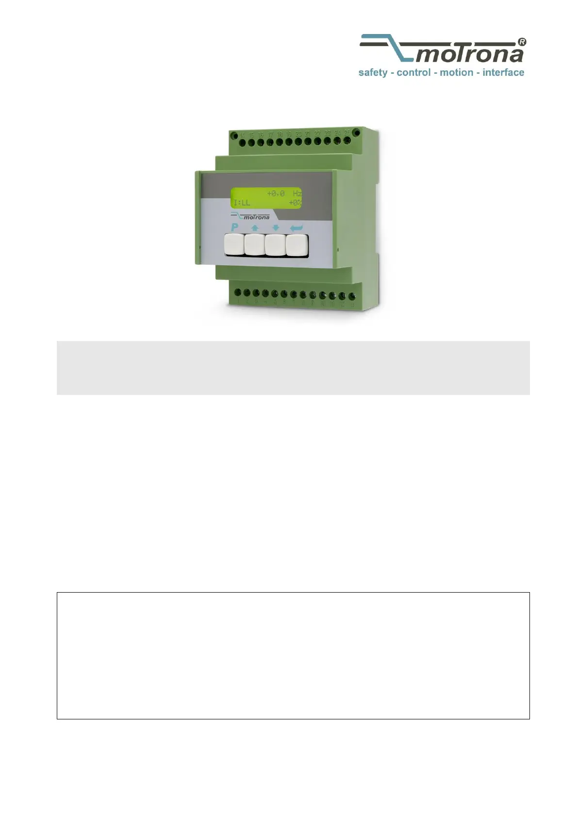
Motrona 6890.5060 Manual

Motrona overvåge 6890.5060

Læs nedenfor 📖 manual på dansk for Motrona 6890.5060 (40 sider) i kategorien overvåge. Denne guide var nyttig for 28 personer og blev bedømt med 4.7 stjerner i gennemsnit af 14.5 brugere

Side 1/40
Operating Manual
motrona GmbH, Zeppelinstraße 16, DE - 78244 Gottmadingen, Tel. +49 (0) 7731 9332-0, Fax +49 (0) 7731 9332-30, info@motrona.com, www.motrona.com
6890.50
6890.50
6890.50
6890.506890.5060, 6890.
60, 6890.
60, 6890.
60, 6890.60, 6890.5061, 6
5061, 6
5061, 6
5061, 65061, 6890.5066, 6
890.5066, 6
890.5066, 6
890.5066, 6890.5066, 6890.50
890.50
890.50
890.50890.5067, 6890.50
67, 6890.50
67, 6890.50
67, 6890.5067, 6890.50
69
69
69
6969
Monitor for speed,
Monitor for speed,
Monitor for speed,
Monitor for speed, Monitor for speed, standstill and direction of rotation with incremental
standstill and direction of rotation with incremental
standstill and direction of rotation with incremental standstill and direction of rotation with incremental encoder signals
encoder signals
encoder signals
encoder signalsencoder signals
Product features:
Product features:
Product features:
Product features: Product features:
Compact and most versatile monitor series for control of
overspeed, underspeed, standstill and direction of rotation
Logical monitoring of remote motion enable signals
Universal inputs for connection to incremental encoders (TTL, RS422 or HTL),
proximity switches, photocells remote TTL signals
Extremely wide frequency range, operating from 0.1 Hz up to 1 MHz
Easy setup by means of four keys and LCD menu
All models include serial RS232 interface
Available devices:
Available devices:
Available devices:
Available devices: Available devices:
6890.5060:
6890.5060:
6890.5060:
6890.5060: 6890.5060: Monitor with 3 programmable output relays and 1 analog output
6890.5061:
6890.5061:
6890.5061:
6890.5061: 6890.5061: Monitor with 3 fast switching transistor outputs and 1 analog output
6890.50
6890.50
6890.50
6890.506890.5066
66
66
6666:
:
:
: : Monitor with 1 analog output only
6890.5067:
6890.5067:
6890.5067:
6890.5067: 6890.5067: Monitor with 3 programmable output relays only
6890.5069:
6890.5069:
6890.5069:
6890.5069: 6890.5069: Monitor with 3 fast switching transistor outputs only
6890_5060_05a_oi_e.doc Mrz- Page 2 / 21 / 40
Version:
Version:
Version:
Version: Version:
Description:
Description:
Description:
Description: Description:
6890.50 _01b_af/kk/hk_07/07 60
First edition in English
6890.50 _02a_af/kk/hk_01/08 60
Commands “Force Relays” and “Freeze Relays” added
6890.50 _03a_af/hk_11/08 60
Command Monitor for remote enable signal
6890.50 _03b_pp_11/11 60
Chapter 6.2.2 “Encoder properties” replaced TTL by HTL
6890.50 _03c_pp_07/12 60
Hint: “Special Menu” is password protected (Chap. 6.2.5)
6890.50 _03d_pp_11/12 60
Changed “Setting Range” for parameter “Wait Time” (code A3)
6890.50 _04a_sn_12/12 60
Additional device 6890.5061 and 6890.50 69
6890.50 _04b_hk/nw_04/13 60
Small corrections
6890.50 _04c_sn_06/14 60
Small corrections Analog-Menu
6890.50 _04d/ag_ /15 60 04
Small corrections Analog-Menu.
New chapter 1. “Safety Instructions and Responsibility”.
6890.5060_04e_ag / Aug- 15
- Analog output 4.13 hint: only V or mA can be used (not both together)
- Analog menu 7.2.7 some hints and a setup example supplemented
- Some smaller corrections and modulations
6890.5060_05a_af / Okt- 16
Parameter Analogue ABS added
Parameter Preselection Mode increased to 9
6890_5060_05a_oi_e.doc Mrz- Page 3 / 21 / 40
Table of Contents
1.
1.
1.
1.1. Safety I
Safety I
Safety I
Safety ISafety Instructions an
nstructions an
nstructions an
nstructions annstructions and Responsibi
d Responsibi
d Responsibi
d Responsibid Responsibility
lity
lity
lity lity .........................................................
.........................................................
.........................................................
..................................................................................................................
5
5
5
55
1.1. General Safety Instructions ................................................................................... 5
1.2. Use according to the intended purpose ................................................................ 5
1.3. Installation ............................................................................................................. 6
1.4. Cleaning, Maintenance and Service Notes ........................................................... 6
2.
2.
2.
2.2. Introduc
Introduc
Introduc
IntroducIntroduction
tion
tion
tion tion ................................................................................................
................................................................................................
................................................................................................
.................................................................................................................................................................................................
.
.
. . 7
7
7
77
3.
3.
3.
3.3. Available
Available
Available
Available Available Models
Models
Models
Models Models
.........................................................................................
.........................................................................................
.........................................................................................
..................................................................................................................................................................................
7
7
7
77
4.
4.
4.
4.4. Electrical
Electrical
Electrical
ElectricalElectrical Connections
Connections
Connections
Connections Connections
.................................................................................
.................................................................................
.................................................................................
..................................................................................................................................................................
8
8
8
88
4.1. 6890.5060 .............................................................................................................. 8
4.2. 6890.5061 .............................................................................................................. 9
4.3. 6890.5066 ............................................................................................................ 10
4.4. 6890.5067 ............................................................................................................ 11
4.5. 6890.5069 ............................................................................................................ 12
4.6. Power Supply ....................................................................................................... 13
4.7. Auxiliary Output for Encoder Supply ................................................................... 13
4.8. Impulse Inputs for Encoders and Sensors ........................................................... 13
4.9. Control Inputs ...................................................................................................... 13
4.10. Serial Interface .................................................................................................... 14
4.11. Relay Outputs K1 K3 (6890.5060 and 6890.5067 only) .................................... 14
4.12. Transistor Outputs K1 K3 (6890.5061 and 6890.5069 only) ............................. 14
4.13. Scalable Analog Output (6890.5060, 6890.5061 and 6890.5066 only) ............... 14
5.
5.
5.
5.5. LCD Display
LCD Display
LCD Display
LCD Display LCD Display and Keys
and Keys
and Keys
and Keysand Keys
................................................................................
................................................................................
................................................................................
................................................................................................................................................................
15
15
15
1515
6.
6.
6.
6.6. Keypad Op
Keypad Op
Keypad Op
Keypad OpKeypad Operation
eration
eration
eration eration ......................................................................................
......................................................................................
......................................................................................
............................................................................................................................................................................
16
16
16
1616
6.1. Normal Operation ................................................................................................ 16
6.2. Keypad Interlock .................................................................................................. 16
6.3. General Setup Procedure ....................................................................................17
6.4. Changing Parameters on the Setting Level ......................................................... 17
6.5. Return from the Menu, Time-Out Function ......................................................... 18
6.6. Reset all Parameters to Factory Default Values ................................................. 18
7.
7.
7.
7.7. Menu Struct
Menu Struct
Menu Struct
Menu StructMenu Structure and P
ure and P
ure and P
ure and Pure and Parameter D
arameter D
arameter D
arameter Darameter Description
escription
escription
escriptionescription
...............................................
...............................................
...............................................
..............................................................................................
19
19
19
1919
7.1. Survey of Menus ................................................................................................. 19
7.2. Parameter Descriptions ....................................................................................... 20
7.2.1. Preselection’s................................................................................................................20
7.2.2. Definitions for the Encoder or Speed Sensor ...............................................................20
7.2.3. Serial Readout Menu ....................................................................................................21
7.2.4. Special-Menu ................................................................................................................22
7.2.5. Key- -Menu Pad ...............................................................................................................22
7.2.6. Command-Menu ............................................................................................................23
6890_5060_05a_oi_e.doc Mrz- Page 4 / 21 / 40
7.2.7. Analog-Menu ................................................................................................................24
7.2.8. Serial Menu ...................................................................................................................25
7.2.9. Switching Menu ..........................................................................................................27
7.2.10. Linear.-Menu .................................................................................................................31
7.2.11. Display Menu ..............................................................................................................32
8.
8.
8.
8.8. Example fo
Example fo
Example fo
Example foExample for Commissionin
r Commissionin
r Commissionin
r Commissioninr Commissioning
g
g
g g
.......................................................................
.......................................................................
.......................................................................
..............................................................................................................................................
33
33
33
3333
9.
9.
9.
9.9. Appendix
Appendix
Appendix
AppendixAppendix
...................................................................................................
...................................................................................................
...................................................................................................
......................................................................................................................................................................................................
35
35
35
3535
9.1. Hints for Use of the Linearization Function ......................................................... 35
9.2. Data Readout via Serial Interface ....................................................................... 36
9.3. “Relay Action”, override relay states by programmed states ............................. 37
9.3.1. Override relay/output states by programmable ON / OFF states ................................37
9.3.2. Freeze the actual switching state of all relays ............................................................37
9.4. Monitoring of remote motion enable signals ...................................................... 38
9.4.1. Definition of a speed window ......................................................................................38
9.4.2. Assignment of a control input ......................................................................................38
9.4.3. Assignment of the control polarity ...............................................................................38
9.4.4. Setting of a Start-up delay time ...................................................................................38
9.4.5. Setting of an appropriate Standstill definition ............................................................38
10.
10.
10.
10.10. Dimensions:
Dimensions:
Dimensions:
Dimensions:Dimensions:
...............................................................................................
...............................................................................................
...............................................................................................
..............................................................................................................................................................................................
39
39
39
3939
11.
11.
11.
11.11. Technical
Technical
Technical
Technical Technical Specificatio
Specificatio
Specificatio
SpecificatioSpecifications
ns
ns
ns ns ............................................................................
............................................................................
............................................................................
........................................................................................................................................................
40
40
40
4040
6890_5060_05a_oi_e.doc Mrz- Page 5 / 21 / 40
1.
1.
1.
1.1.
Safety Instr
Safety Instr
Safety Instr
Safety InstrSafety Instructions and
uctions and
uctions and
uctions anductions and Responsibility
Responsibility
Responsibility
Responsibility Responsibility
1.1.
1.1.
1.1.
1.1.1.1. General Safety
General Safety
General Safety
General SafetyGeneral Safety Instructions
Instructions
Instructions
Instructions Instructions
This operation manual is a significant component of the unit and includes important rules and
hints about the installation, function and usage. Non-observance can result in damage and/or
impairment of the functions to the unit or the machine or even in injury to persons using the
equipment!
Please read the following instruct
Please read the following instructPlease read the following instructions carefully before operating the device and
ions carefully before operating the device and
ions carefully before operating the device andions carefully before operating the device and observe all
observe all
observe all
observe all observe all
safety and warning instruct
safety and warning instructsafety and warning instructions! Keep the manual for later use.
ions! Keep the manual for later use.
ions! Keep the manual for later use. ions! Keep the manual for later use.
A pertinent qualification of the respective staff is a fundamental requirement in order to use
these manual. The unit must be installed, connected and put into operation by a qualified
electrician.
Liability exclusion:
Liability exclusion:Liability exclusion: The manufacturer is not liable for personal injury and/or damage to property
and for consequential damage, due to incorrect handling, installation and operation. Further
claims due to errors in the operation manual as well as misinterpretations are excluded from
liability.
In addition the manufacturer reserve the right to modify the hardware, software or operation
manual at any time and without prior notice. Therefore, there might be minor differences
between the unit and the descriptions in operation manual.
The raiser respectively positioner is exclusively responsible for the safety of the system and
equipment where the unit will be integrated.
During installation or maintenance all general and also all country- and application-specific safety
rules and standards must be observed.
If the device is used in processes, where a failure or faulty operation could damage the system or
injure persons, appropriate precautions to avoid such consequences must be taken.
1.2.
1.2.
1.2.
1.2.1.2. Use according to
Use according to
Use according to
Use according toUse according to the inten
the inten
the inten
the inten the intended purpose
ded purpose
ded purpose
ded purpose ded purpose
The unit is intended exclusively for use in industrial machines, constructions and systems. Non-
conforming usage does not correspond to the provisions and lies within the sole responsibility of
the user. The manufacturer is not liable for damages which has arisen through unsuitable and
improper use.
Please note that device may only be installed in proper form and used in a technically perfect
condition in accordance to the Technical Specifications (see chapter and 11).
The device is not suitable for operation in explosion-proof areas or areas which are excluded by
the EN 61010-1 standard.
6890_5060_05a_oi_e.doc Mrz- Page 6 / 21 / 40
1.3.
1.3.
1.3.
1.3.1.3. Installation
Installation
Installation
Installation Installation
The device is only allowed to be installed and operated within the permissible temperature range.
Please ensure an adequate ventilation and avoid all direct contact between the device and hot or
aggressive gases and liquids.
Before installation or maintenance, the unit must be disconnected from all voltage-sources.
Further it must be ensured that no danger can arise by touching the disconnected voltage-
sources.
Devices which are supplied by AC-voltages, must be connected exclusively by switches,
respectively circuit-breakers with the low voltage network. The switch or circuit-breaker must be
placed as near as possible to the device and further indicated as separator.
Incoming as well as outgoing wires and wires for extra low voltages (ELV) must be separated
from dangerous electrical cables (SELV circuits) by using a double resp. increased isolation.
All selected wires and isolations must be conform to the provided voltage- and temperature-
ranges. Further all country- and application-specific standards, which are relevant for structure,
form and quality of the wires, must be ensured. Instructions about the permissible wire cross-
sections for wiring are described in the chapter Technical Specifications
11 ”.
Before first start-up it must be ensured that all connections and wires are firmly seated and
secured in the screw terminals. All (inclusively unused) terminals must be fastened by turning the
relevant screws clockwise up to the stop.
Overvoltages at the connections must be limited to values in accordance to the overvoltage
category II.
For placement, wiring, environmental conditions, as well as shielding and earthing/grounding of
the supply lines, the general standards of industrial automation industry and the specific
shielding instructions of the manufacturer are valid. Please find all respective hints and rules on
www.motrona.com/download.html --> “[General EMC Rules for Wiring, Screening and Earthing]”.
1.4.
1.4.
1.4.
1.4.1.4. Cleaning, Mainte
Cleaning, Mainte
Cleaning, Mainte
Cleaning, MainteCleaning, Maintenance and Service Notes
nance and Service Notes
nance and Service Notesnance and Service Notes
To clean the front of the unit please use only a slightly damp (not wet!), soft cloth. For the rear no
cleaning is necessary. For an unscheduled, individual cleaning of the rear the maintenance staff
or assembler is self-responsible.
During normal operation no maintenance is necessary. In case of unexpected problems, failures
or malfunctions the device must be shipped back to the manufacturer for checking, adjustment
and reparation (if necessary). Unauthorized opening and repairing can have negative effects or
failures to the protection-measures of the unit.
6890_5060_05a_oi_e.doc Mrz- Page 8 / 21 / 40
4.
4.
4.
4.4. Electrical Conn
Electrical Conn
Electrical Conn
Electrical ConnElectrical Connections
ections
ections
ections ections
4.1.
4.1.
4.1.
4.1.4.1. 6890.50
6890.50
6890.50
6890.506890.50
60
60
60
6060
1 2 3 4 5 6 7 8 9 10 11 12 13
14 15 16 17 18 19 20 21 22 23 24 25
GND (-)
GND
GND
GND
RxD
TxD
K1
K2
K3
+Power input
+5,2V
A
/A
B
/B
0 - 10 V
0/4 - 20 mA
Control 1
Control 2
Aux. Output
+5,2V
Impulse inputs
for encoders and
sensors
Power supply
17 - 30 VDC
Control
inputs
Analogue
output
Serial RS232-
interface
NO
NC
C
NO
NC
C
NO
NC
C
Relay K1
Relay K2
Relay K3
Terminal
Terminal
Terminal
Terminal Terminal
Text
Text
Text
Text Text
Function
Function
Function
Function Function
01
01
01
0101
GND
GND, common minus potential
02
02
02
0202
Vin
Power input, +17 ... 30 VDC
03
03
03
0303
GND
GND, common minus potential
04
04
04
0404
+5,2V
Aux. output 5.2 V / 200 mA
05
05
05
0505
A
Impulse input, channel A
06
06
06
0606
/A
Impulse input, channel /A (=A invert ed)
07
07
07
0707
B
Impulse input, channel B
08
08
08
0808
/B
Impulse input, channel /B (=B inverted)
09
09
09
0909
Control 2
Control input with programmable function
10
10
10
1010
Control 1
Control input with programmable function
11
11
11
1111
GND
GND, common minus potential
12
12
12
1212
+10V Out
Analog output 0 ... 10 V
13
13
13
1313
20mA out
Analog output 0 ... 20 mA
14
14
14
1414
GND
GND, common minus potential
15
15
15
1515
RXD
Serial RS232 interface, data input
16
16
16
1616
TXD
Serial RS232 interface, data output
17
17
17
1717
K1NO
Relay 1, normally open contact
18
18
18
1818
K1NC
Relay 1, normally closed conta ct
19
19
19
1919
K1C
Relay 1, common contact
20
20
20
2020
K2NO
Relay 2, normally open contact
21
21
21
2121
K2NC
Relay 2, normally closed contact
22
22
22
2222
K2C
Relay 2, common contact
23
23
23
2323
K3NO
Relay 3, normally open contact
24
24
24
2424
K3NC
Relay 3, normally closed contact
25
25
25
2525
K3C
Relay 3, common contact
6890_5060_05a_oi_e.doc Mrz- Page 9 / 21 / 40
4.2.
4.2.
4.2.
4.2.4.2. 6890.50
6890.50
6890.50
6890.506890.50
61
61
61
6161
1 2 3 4 5 6 7 8 9 10 11 12 13
14 15 16 17 18 19 20 21 22 23 24 25
GND (-)
GND
GND
GND
RxD
TxD
+Power supply
+5,2V
A
/A
B
/B
0 - 10 V
0/4 - 20 mA
Control 1
Control 2
Aux. output
+5,2V
Impulse inputs
for encoders and
sensors
Power supply
17 - 30 VDC
Control
inputs
Analogue
output
Serial RS232-
interface
Com + (5-30 V/DC)
GND
NC
K1 out
K2 out
K3 out
Terminal
Terminal
Terminal
Terminal Terminal
Text
Text
Text
Text Text
Function
Function
Function
Function Function
01
01
01
0101
GND
GND, common minus potential
02
02
02
0202
Vin
Power input, +17 ... 30 VDC
03
03
03
0303
GND
GND, common minus potential
04
04
04
0404
+5,2V
Aux. output 5.2 V / 200 mA
05
05
05
0505
A
Impulse input, channel A
06
06
06
0606
/A
Impulse input, channel /A (=A inverted)
07
07
07
0707
B
Impulse input, channel B
08
08
08
0808
/B
Impulse input, channel /B (=B inverted)
09
09
09
0909
Control 2
Control input with programmable function
10
10
10
1010
Control 1
Control input with programmable function
11
11
11
1111
GND
GND, common minus potential
12
12
12
1212
+10V Out
Analog output 0 ... 10 V
13
13
13
1313
20mA out
Analog output 0 ... 20 mA
14
14
14
1414
GND
GND, common minus potential
15
15
15
1515
RXD
Serial RS232 interface, data input
16
16
16
1616
TXD
Serial RS232 interface, data output
17
17
17
1717
NC
Not connected
18
18
18
1818
NC
Not connected
19
19
19
1919
NC
Not connected
20
20
20
2020
NC
Not connected
21
21
21
2121
GND
GND, common minus potential
22
22
22
2222
Com +
Common positive input for transistor outputs K1-K3
23
23
23
2323
K1 out
Output K1, transistor PNP 30 V, 350 mA
24
24
24
2424
K2 out
Output K2, transistor PNP 30 V, 350 mA
25
25
25
2525
K3 out
Output K3, transistor PNP 30 V, 350 mA
6890_5060_05a_oi_e.doc Mrz- Page / 21 10 / 40
4.3.
4.3.
4.3.
4.3.4.3. 6890.50
6890.50
6890.50
6890.506890.50
66
66
66
6666
1 2 3 4 5 6 7 8 9 10 11 12 13
14 15 16 17 18 19 20 21 22 23 24 25
GND (-)
GND
GND
GND
RxD
TxD
+Power supply
+5,2V
A
/A
B
/B
0 - 10 V
0/4 - 20 mA
Control 1
Control 2
Aux. Output
+5,2V
Impulse input
for encoders and
sensors
Power supply
17 - 30 VDC
Control
inputs
Analogue
output
Serial RS232-
interface
NC
Terminal
Terminal
Terminal
Terminal Terminal
Text
Text
Text
Text Text
Function
Function
Function
Function Function
01
01
01
0101
GND
GND, common minus potential
02
02
02
0202
Vin
Power input, +17 ... 30 VDC
03
03
03
0303
GND
GND, common minus potential
04
04
04
0404
+5,2V
Aux. output 5.2 V / 200 mA
05
05
05
0505
A
Impulse input, channel A
06
06
06
0606
/A
Impulse input, channel /A (=A inverted)
07
07
07
0707
B
Impulse input, channel B
08
08
08
0808
/B
Impulse input, channel /B (=B inverted)
09
09
09
0909
Control 2
Control input with programmable function
10
10
10
1010
Control 1
Control input with programmable function
11
11
11
1111
GND
GND, common minus potential
12
12
12
1212
+10V Out
Analog output 0 ... 10 V
13
13
13
1313
20mA out
Analog output 0 ... 20 mA
14
14
14
1414
GND
GND, common minus potential
15
15
15
1515
RXD
Serial RS232 interface, data input
16
16
16
1616
TXD
Serial RS232 interface, data output
17
17
17
1717
NC
Not connected
18
18
18
1818
NC
Not connected
19
19
19
1919
NC
Not connected
20
20
20
2020
NC
Not connected
21
21
21
2121
NC
Not connected
22
22
22
2222
NC
Not connected
23
23
23
2323
NC
Not connected
24
24
24
2424
NC
Not connected
25
25
25
2525
NC
Not connected
6890_5060_05a_oi_e.doc Mrz- Page / 21 11 / 40
4.4.
4.4.
4.4.
4.4.4.4. 6890.50
6890.50
6890.50
6890.506890.50
67
67
67
6767
1 2 3 4 5 6 7 8 9 10 11 12 13
14 15 16 17 18 19 20 21 22 23 24 25
GND (-)
GND
GND
GND
RxD
TxD
K1
K2
K3
+Power supply
+5,2V
A
/A
B
/B
Control 1
Control 2
Aux. output
+5,2V
Impulse inputs
for encoders and
sensors
Power supply
17 - 30 VDC
Control
inputs
NC
Serial RS232-
interface
NO
NC
C
NO
NC
C
NO
NC
C
Relay K1
Relay K2
Relay K3
Terminal
Terminal
Terminal
Terminal Terminal
Text
Text
Text
Text Text
Fu
Fu
Fu
FuFunction
nction
nction
nction nction
01
01
01
0101
GND
GND, common minus potential
02
02
02
0202
Vin
Power input, +17 ... 30 VDC
03
03
03
0303
GND
GND, common minus potential
04
04
04
0404
+5,2V
Aux. output 5.2 V / 200 mA
05
05
05
0505
A
Impulse input, channel A
06
06
06
0606
/A
Impulse input, channel /A (=A inverted)
07
07
07
0707
B
Impulse input, channel B
08
08
08
0808
/B
Impulse input, channel /B (=B inverted)
09
09
09
0909
Control 2
Control input with programmable function
10
10
10
1010
Control 1
Control input with programmable function
11
11
11
1111
GND
GND, common minus potential
12
12
12
1212
NC
Not connected
13
13
13
1313
NC
Not connected
14
14
14
1414
GND
GND, common minus potential
15
15
15
1515
RXD
Serial RS232 interface, data input
16
16
16
1616
TXD
Serial RS232 interface, data output
17
17
17
1717
K1NO
Relay 1, normally open contact
18
18
18
1818
K1NC
Relay 1, normally closed contact
19
19
19
1919
K1C
Relay 1, common contact
20
20
20
2020
K2NO
Relay 2, normally open contact
21
21
21
2121
K2NC
Relay 2, normally closed contact
22
22
22
2222
K2C
Relay 2, common contact
23
23
23
2323
K3NO
Relay 3, normally open contact
24
24
24
2424
K3NC
Relay 3, normally closed contact
25
25
25
2525
K3C
Relay 3, common contact
6890_5060_05a_oi_e.doc Mrz- Page / 21 12 / 40
4.5.
4.5.
4.5.
4.5.4.5. 6890.50
6890.50
6890.50
6890.506890.50
69
69
69
6969
1 2 3 4 5 6 7 8 9 10 11 12 13
14 15 16 17 18 19 20 21 22 23 24 25
GND (-)
GND
GND
GND
RxD
TxD
+Power supply
+5,2V
A
/A
B
/B
Control 1
Control 2
Aux. output
+5,2V
Impulse inputs
for encoders and
sensors
Power supply
17 - 30 VDC
Control
inputs
NC
Serial Rs232-
interface
Com + (5-30 V/DC)
GND
NC
K1 out
K2 out
K3 out
Terminal
Terminal
Terminal
Terminal Terminal
Tex
Tex
Tex
TexText
t
t
t t
Function
Function
Function
Function Function
01
01
01
0101
GND
GND, common minus potential
02
02
02
0202
Vin
Power input, +17 ... 30 VDC
03
03
03
0303
GND
GND, common minus potential
04
04
04
0404
+5,2V
Aux. output 5.2 V / 200 mA
05
05
05
0505
A
Impulse input, channel A
06
06
06
0606
/A
Impulse input, channel /A (=A inverted)
07
07
07
0707
B
Impulse input, channel B
08
08
08
0808
/B
Impulse input, channel /B (=B inverted)
09
09
09
0909
Control 2
Control input with programmable function
10
10
10
1010
Control 1
Control input with programmable function
11
11
11
1111
GND
GND, common minus potential
12
12
12
1212
NC
Not connected
13
13
13
1313
NC
Not connected
14
14
14
1414
GND
GND, common minus potential
15
15
15
1515
RXD
Serial RS232 interface, data input
16
16
16
1616
TXD
Serial RS232 interface, data output
17
17
17
1717
NC
Not connected
18
18
18
1818
NC
Not connected
19
19
19
1919
NC
Not connected
20
20
20
2020
NC
Not connected
21
21
21
2121
GND
GND, common minus potential
22
22
22
2222
Com +
Common positive input for transistor outputs K1-K3
23
23
23
2323
K1 out
Output K1, transistor PNP 30 V, 350 mA
24
24
24
2424
K2 out
Output K2, transistor PNP 30 V, 350 mA
25
25
25
2525
K3 out
Output K3, transistor PNP 30 V, 350 mA
6890_5060_05a_oi_e.doc Mrz- Page / 21 13 / 40
4.6.
4.6.
4.6.
4.6.4.6.
Power Supply
Power Supply
Power Supply
Power Supply Power Supply
The units require a DC supply from 17 to 30 V which must be applied to terminals 1 and 2.
Depending on the input voltage level and internal states, the power consumption may vary and
lies in a range of about 70 mA with a 24 V input (plus encoder currents taken from the auxiliary
voltage output).
4.7.
4.7.
4.7.
4.7.4.7.
Auxiliary Outpu
Auxiliary Outpu
Auxiliary Outpu
Auxiliary OutpuAuxiliary Output for Encoder Supply
t for Encoder Supply
t for Encoder Supplyt for Encoder Supply
Terminals 4 and 3 provide a +5.2 VDC / 200 mA auxiliary output for supply of encoders and
sensors.
4.8.
4.8.
4.8.
4.8.4.8.
Impulse Input
Impulse Input
Impulse Input
Impulse InputImpulse Inputs for Encoders and Sensor
s for Encoders and Sensor
s for Encoders and Sensors for Encoders and Sensors
s
s
s s
The setup menu of the unit allows individual setting of the desired characteristics of the signal
inputs. According to the application the units will accept single-channel signals (input A only with
no direction information) as well as dual channel signals A/B including information of the
direction of rotation. The following input formats and levels are acceptable:
symmetric differential input with RS422 format A, /A, B, /B
asymmetric (single-ended) TTL levels (A and/or B only without inverted channels)
HTL level 10 ... 30 V, alternatively differential (A, /A, B, /B) or single-ended
(A and B only, without inverted channels)
Signals from proximity switches or photocells providing HTL level (10 ... 30 V)
NAMUR (2-wire) signals
4.9.
4.9.
4.9.
4.9.4.9.
Control Inputs
Control Inputs
Control Inputs
Control Inputs Control Inputs
Two programmable control inputs allow the assignment of functions like remote start- -delay, up
reset of relay lock, hardware interlock of the keypad and similar.
Both inputs provide PNP characteristics and require HTL level. Also it is possible to set the control
function to "active LOW" or "active HIGH".
For evaluation of dynamic events the desired "active edge" can be set (rising or falling edge)
6890_5060_05a_oi_e.doc Mrz- Page / 21 14 / 40
4.10.
4.10.
4.10.
4.10.4.10.
Serial Interfa
Serial Interfa
Serial Interfa
Serial InterfaSerial Interface
ce
ce
ce ce
The serial RS232 interface in general may be used
for easy setup and commissioning of the units (with use of the OS32 operator software)
to change settings and parameters by PC or PLC during the operation
to read out internal states and actual measuring values by PC or PLC
The subsequent drawing shows how to link the monitor with a PC, using the standard
9-pin SUB-D-9 connector
2
3
5
RxD RxD
TxDTxD
GND
Screen
PC
DZ 260
DZ 261
DZ 266
DZ 267
DZ 269
15
(Sub-D-9)
16
14
4.11.
4.11.
4.11.
4.11.4.11.
Relay Outpu
Relay Outpu
Relay Outpu
Relay OutpuRelay Outputs K1
ts K1
ts K1
ts K1 ts K1 K3 (6890
K3 (6890
K3 (6890
K3 (6890 K3 (6890.50
.50
.50
.50.50 and 6890.50
and 6890.50
and 6890.50
and 6890.50 and 6890.5067 only)
67 only)
67 only)
67 only) 67 only)
60
60
60
6060
The units provide three programmable relay outputs (all dry changeover), providing a switching
capability of 30 V / 2 A DC or 125 V / 0.6 A AC or 230 V / 0.3 A AC. Both, switching
characteristics and monitoring function may be programmed for each of the relays individually.
4.12.
4.12.
4.12.
4.12.4.12.
Transistor
Transistor
Transistor
TransistorTransistor Outputs K1
Outputs K1
Outputs K1
Outputs K1 Outputs K1
K3 (6890.5061 an
K3 (6890.5061 an
K3 (6890.5061 an
K3 (6890.5061 anK3 (6890.5061 and 6890.5069 on
d 6890.5069 on
d 6890.5069 on
d 6890.5069 ond 6890.5069 only)
ly)
ly)
ly) ly)
The units provide three outputs with programmable switching characteristics.
K1 K3 are fast-switching and short-circuit-proof transistor outputs with a switching capability of
5 ... 30 V / 350 mA each. The switching voltage of the outputs must be applied remotely to the
Com+ input (terminal 22). Both, switching characteristics and monitoring function may be
programmed for each of the outputs individually.
4.13.
4.13.
4.13.
4.13.4.13.
Scalable
Scalable
Scalable
Scalable Scalable Analog Output (6890
Analog Output (6890
Analog Output (6890
Analog Output (6890Analog Output (6890.5060, 6890.50
.5060, 6890.50
.5060, 6890.50
.5060, 6890.50.5060, 6890.5061 and 6890.5066
61 and 6890.5066
61 and 6890.5066
61 and 6890.506661 and 6890.5066 only)
only)
only)
only) only)
The units provide a voltage output with a +/- V range (max. load 2 mA) and a current output 10
with ranges 0 / 4 ... 20 mA (burden Ohm), however only one of the two can be used at a 0 270
time. Beginning and end of the desired conversion range can be set by the operator menu (see
section ). The common potential of both outputs refers to GND.
7.2.7
The total resolution is 14 bits. A settling time of approx. 200 µs. is required. The overall response
time of the analog outputs primarily depends on the selected Sampling Time setting. After
volatile jumps of the input signal, the analog outputs may need up to two Sampling Time cycles
(plus 200 µsec.) to stabilize.
Important n
Important n
Important n
Important nImportant n must not
must not
must not
must notmust not be used together
be used together
be used together
be used together be used together
ot
ot
ot
otote: “voltage out” and “current o
e: “voltage out” and “current o
e: “voltage out” and “current oe: “voltage out” and “current out”
ut”
ut”
ut” ut” .
.
.
. .
Please do never conn
Please do never connPlease do never connect mA and V simultaneously!
ect mA and V simultaneously!
ect mA and V simultaneously! ect mA and V simultaneously!
6890_5060_05a_oi_e.doc Mrz- Page / 21 15 / 40
5.
5.
5.
5.5. LCD Display and
LCD Display and
LCD Display and
LCD Display andLCD Display and Keys
Keys
Keys
Keys Keys
The units provide a back-lit LCD display with 2 lines at 16 characters each, and four keys for setup
and command control.
During the setup procedure the LCD display indicates the menu with all parameter texts and the
set values of the parameters.
During normal operation, the LCD display indicates the following information:
Actual speed value
Input frequency, scaled in user units
+156.5 Hz
I: LH O: COO +47 %
Analogue output (not with DZ267, DZ269)
Actual output level in % of full scale
O: Outputs (not with DZ266)
Actual switching states of relays/transistor outputs
(Rel1, Rel2, Rel3)/(out1, out2, out3)
C = Closed, O = Open
I: Inputs
Actual logical state of inputs
(Control1, Control2)
L = Low, H = High
The "Display Menu" allows free scaling of the speed measuring values and the speed-related
parameters to any kind of engineering units.
6890_5060_05a_oi_e.doc Mrz- Page / 21 16 / 40
6.
6.
6.
6.6. Keypad Operation
Keypad Operation
Keypad Operation
Keypad OperationKeypad Operation
A summary of all parameters and a detailed description of parameter functions is available under
section 6.
For all operation, the units provide four keys which subsequently will be named as shown below:
PROG
PROG
PROG
PROG PROG
UP
UP
UP
UPUP
DOWN
DOWN
DOWN
DOWN DOWN
ENTER
ENTER
ENTER
ENTER ENTER
The key functions depend on the actual operating state of the units. Basically p16-we have to
distinguish between Normal
Normal
Normal
Normal Normal Operation
Operation
Operation
OperationOperation Setup Operation
Setup Operation
Setup Operation
Setup OperationSetup Operation and
6.1.
6.1.
6.1.
6.1.6.1.
Normal Opera
Normal Opera
Normal Opera
Normal OperaNormal Operation
tion
tion
tion tion
While in normal operation state, the units monitor the speed according to the selected
operational parameters and settings. Each of the front keys provides the command functions as
attached to it upon setup in the "Command Menu"
6.2.
6.2.
6.2.
6.2.6.2.
Keypad Inte
Keypad Inte
Keypad Inte
Keypad InteKeypad Interlock
rlock
rlock
rlock rlock
There is a 3-stage conception to protect the keys against unauthorized changes of the
configuration respectively against activation of commands.
Stage
Stage
Stage
Stage Stage
Protected
Protected
Protected
Protected Protected
Range
Range
Range
Range Range
Protection
Protection
Protection
Protection Protection
by
by
by
byby
Key Operations
Key Operations
Key Operations
Key Operations Key Operations
Change of Parameters
Change of ParametersChange of Parameters
Co
Co
Co
CoCommands
mmands
mmands
mmands mmands
1
1
1
1 1
---
---
permitted
permitted
2
2
2
2 2
Menu
Password upon
activation of menu
Protection of selectable parts of the menu
via password
permitted
3
3
3
3 3
Keyboard
Hardware-Latch 1
interlocked
permitted
Hardware Latch 2
All functions interlocked
The "Key Pad" menu allows to define an individual password for each group of parameters. This
function can be used to provide individual access rights to different operators. Upon access to an
interlocked section the unit asks for the corresponding password. If the correct password is not
entered in time, the unit denies access and automatically returns to normal operation.
The hardware latch function can be activated and deactivated by one of the Control Inputs, or by
means of serial access to the corresponding locking register.
Using the Hardware Latch funct
Using the Hardware Latch functUsing the Hardware Latch function may accidentally cause a tot
ion may accidentally cause a tot
ion may accidentally cause a totion may accidentally cause a total locking of all
al locking of all
al locking of all
al locking of all al locking of all
functions, when the Cont
functions, when the Contfunctions, when the Control Inputs characteristics have been set
rol Inputs characteristics have been set
rol Inputs characteristics have been setrol Inputs characteristics have been set inauspiciously.
inauspiciously.
inauspiciously.
inauspiciously. inauspiciously.
In this exceptional case you can release the key functions again by either
a) ap plying the correct logical state (High or Low) to the inputs
b) or resetting the parameters to their default values (see section )
6.6
c) or change the parameters being responsible for the locking by PC
P
6890_5060_05a_oi_e.doc Mrz- Page / 21 17 / 40
6.3.
6.3.
6.3.
6.3.6.3.
General Set
General Set
General Set
General Set General Setup Procedure
up Procedure
up Procedure
up Procedure up Procedure
To change over from normal operation to the setup state, please keep down the PROG key for at
least 2 seconds. After this the menu appears and you can select one of the menu groups.
Inside each group you can select the desired parameter and edit the setting according to need.
After this you are free to edit more parameters, or to return to normal operation.
The function of the different keys during setup is shown in the table below.
Key
Key
Key
Key Key
Menu Level
Menu Level
Menu Level
Menu Level Menu Level
Parameter Level
Parameter Level
Parameter Level
Parameter Level Parameter Level
Setting Level
Setting Level
Setting Level
Setting Level Setting Level
PROG
PROG
PROG
PROG PROG
Save settings and return
to normal operation
Return to Menu Level
Check entry, store result,
then go back to Parameter
Level
UP
UP
UP
UPUP
Switch over to next menu
Select next parameter
Increment the highlighted
digit or scroll the setting
upwards
DOWN
DOWN
DOWN
DOWN DOWN
Go back to previous menu
Select previous parameter
Decrement the highlighted
digit or scroll the setting
downwards
ENTER
ENTER
ENTER
ENTER ENTER
Switch over to the
Parameter Level of the
current menu
Switch over to
Setting Level
Shifts the highlighted digit
one position to the left, or
from utmost left to utmost
right
6.4.
6.4.
6.4.
6.4.6.4.
Changing Para
Changing Para
Changing Para
Changing ParaChanging Parameters on the Sett
meters on the Sett
meters on the Sett
meters on the Settmeters on the Setting Level
ing Level
ing Level
ing Leveling Level
With signed parameters, the front digit can only be changed between „+“
„+“
„+“
„+“„+“ (positive) and
-
-
-
--
(negative). The subsequent example explains how to change a parameter from originally to
1024
1024
1024
10241024
a new value of
250 000
250 000
250 000
250 000250 000.
The example assumes that you are already on the Setting Level, i.e. you have already selected
the corresponding parameter and read its actual value on the display. Highlighted (blinking) digits
are marked by background colour and indicate the cursor position.
6890_5060_05a_oi_e.doc Mrz- Page / 21 18 / 40
No.
No.
No.
No. No.
Display
Display
Display
Display Display
Key action
Key action
Key action
Key action Key action
Comment
Comment
Comment
Comment Comment
00
001024
001024
001024
001024001024
The actual value 1024 is displayed, with
the last digit blinking
01
4 x
Change last digit to 0
02
001020
001020
001020
001020001020
Shift cursor to left
03
001020
001020
001020
001020001020
2 x
Change highlighted digit to 0
04
001000
001000
001000
001000001000
2 x
Shift curser to left by 2 positions
05
001000
001000
001000
001000001000
Change highlighted digit to 0
06
000000
000000
000000
000000000000
Shift cursor to left
07
000000
000000
000000
000000000000
5 x
Change highlighted digit to 5
08
050000
050000
050000
050000050000
Shift cursor to left
09
050000
050000
050000
050000050000
2 x
Change highlighted digit to 2
10
250000
250000
250000
250000250000
Save new setting and return to
Parameter Level
6.5.
6.5.
6.5.
6.5.6.5.
Return from th
Return from th
Return from th
Return from thReturn from the Menu, Time
e Menu, Time
e Menu, Time
e Menu, Timee Menu, Time-Out Function
-Out Function
-Out Function
-Out Function -Out Function
At any time the PROG key changes the Menu by one level backwards or fully back to the normal
operation mode. The menu also switches automatically one level backwards, every time when for
10 seconds no key has been touched (Time-Out-Function).
6.6.
6.6.
6.6.
6.6.6.6.
Reset all Par
Reset all Par
Reset all Par
Reset all ParReset all Parameters to Factory Defau
ameters to Factory Defau
ameters to Factory Defauameters to Factory Default Values
lt Values
lt Values
lt Valueslt Values
If applicable, the whole set of parameters can be reset to factory default values (e.g. because a
code for the keypad interlocking has been forgotten, or because the unit does no more work
correctly for reasons of bad settings). All default values are indicated in the following parameter
tables.
To execute this Reset procedure, you have to take the following steps:
Power the unit down
Power the unit down
Power the unit down
Power the unit down Power the unit down
Press
Press
Press
Press Press
and
and
and
and and
simultaneously
simultaneously
simultaneously
simultaneously simultaneously
Switch power on with b
Switch power on with bSwitch power on with both keys held down
oth keys held down
oth keys held down
oth keys held down oth keys held down
When
When
When
WhenWhen execute this action, please be aware t
execute this action, please be aware t
execute this action, please be aware t execute this action, please be aware that all parameter settings
hat all parameter settings
hat all parameter settings hat all parameter settings
will be lost and the whole setup proced
will be lost and the whole setup procedwill be lost and the whole setup procedure must be repeated!
ure must be repeated!
ure must be repeated! ure must be repeated!
6890_5060_05a_oi_e.doc Mrz- Page / 21 19 / 40
7.
7.
7.
7.7. Menu Struct
Menu Struct
Menu Struct
Menu StructMenu Structure and Parameter
ure and Parameter
ure and Parameter
ure and Parameter ure and Parameter Description
Description
Description
DescriptionDescription
All parameters are combined to groups, arranged in several menus. Settings are only necessary
for ameters which are really relevant for the individual application. par
7.1.
7.1.
7.1.
7.1.7.1.
Survey of Men
Survey of Men
Survey of Men
Survey of MenSurvey of Menus
us
us
us us
This section provides an overview of the menus and their assignments to the different functions
of the units. The menu names are printed bold, and associated parameters are arrayed directly
under the menu names.
Menu texts are in English language, according to the presentation on the LCD display
Preselect.-Menu
Preselect.-Menu
Preselect.-Menu
Preselect.-MenuPreselect.-Menu
*
Encoder-Menu
Encoder-Menu
Encoder-Menu
Encoder-Menu Encoder-Menu
Ser.Readout Menu
Ser.Readout Menu
Ser.Readout Menu
Ser.Readout Menu Ser.Readout Menu
Special-Men
Special-Men
Special-Men
Special-MenSpecial-Menu
u
u
uu
Preselection 1
Encoder Proper
Multiplier
Linear Mode**
Preselection 2
Direction
Divider
Freq. Control
Preselection 3
Sampling Time
Offset
Input Filter
Wait Time
Filter
Set Value
Key-Pad-Menu
Key-Pad-Menu
Key-Pad-Menu
Key-Pad-Menu Key-Pad-Menu
Command-Menu
Command-Menu
Command-Menu
Command-MenuCommand-Menu
***
Analog-Menu
Analog-Menu
Analog-Menu
Analog-MenuAnalog-Menu
**
Serial-Menu
Serial-Menu
Serial-Menu
Serial-Menu Serial-Menu
Protect Menu M01
Key Up Func.
Analogue Format
Unit Number
Protect Menu M02
Key Down Func.
Analogue Start
Serial Baud Rate
Protect Menu M03
Key Enter Func.
Analogue End
Serial Format
Input 1 Config.
Analogue Swing
Serial Protocol
Protect Menu M09
Input 1 Func.
Analogue Offset
Analogue ABS
Serial Timer
Protect Menu M10
Input 2 Config.
Register Code
Protect Menu M11
Input 2 Func.
Switching-Menu
Switching-Menu
Switching-Menu
Switching-MenuSwitching-Menu
*
Linear.-Menu
Linear.-Menu
Linear.-Menu
Linear.-MenuLinear.-Menu
**
Display-Menu
Display-Menu
Display-Menu
Display-Menu Display-Menu
Pulse Time 1
P1(x)
Up-Date-Time
Pulse Time 2
P1(y)
Display Mode
Pulse Time 3
P2(x)
Encoder Factor
Hysteresis 1
P2(y)
Multiplier
Hysteresis 2
..
Hysteresis 3
P14(x)
Preselect Mode 1
P14(y)
Preselect Mode 2
P15(x)
Preselect Mode 3
P15(y)
Output Polarity
Start up Mode
Start up Relay
(*)
(*)
(*)
(*)(*) not relevant with 6890.50 66
(**)
(**)
(**)
(**)(**) not relevant with 6890.5067, 6890.50 69
(***)
(***)
(***)
(***)(***) partially inactive with 6890.5066
Lock Relay
Standstill Time
6890_5060_05a_oi_e.doc Mrz- Page / 21 20 / 40
7.2.
7.2.
7.2.
7.2.7.2.
Parameter
Parameter
Parameter
ParameterParameter Descriptions
Descriptions
Descriptions
Descriptions Descriptions
7.2.1.
7.2.1.
7.2.1.
7.2.1.7.2.1. Preselection’s
Preselection’s
Preselection’s
Preselection’sPreselection’s
Preselection paramet
Preselection parametPreselection parameters are
ers are
ers are
ers are ers are relevant for mod
relevant for mod
relevant for mod
relevant for mod relevant for model 6890.50
el 6890.50
el 6890.50
el 6890.50el 6890.50
not
not
not
notnot 66
66
66
6666
These parameters assign the desired switching points to the relays/outputs. The preselection’s
use the same engineering units as the display of the actual speed (see Display-Menu
Display-Menu
Display-Menu
Display-MenuDisplay-Menu).
Preselection Menu
Preselection Menu
Preselection Menu
Preselection Menu Preselection Menu
Code
Code
Code
Code Code
Setting Range
Setting Range
Setting Range
Setting Range Setting Range
Default
Default
Default
Default Default
Preselection1
Preselection1
Preselection1
Preselection1Preselection1
Switching point of re
Switching point of reSwitching point of relay 1/ out 1
lay 1/ out 1
lay 1/ out 1
lay 1/ out 1 lay 1/ out 1 (engineering units)
„00“
-1 000 000.0 ... +1 000 000.0
100.0
Preselection2
Preselection2
Preselection2
Preselection2 Preselection2
Switching point of re
Switching point of reSwitching point of relay 2/ out 2
lay 2/ out 2
lay 2/ out 2
lay 2/ out 2 lay 2/ out 2
(engineering units)
„01“
-1 000 000.0 ... +1 000 000.0
200.0
Preselection3
Preselection3
Preselection3
Preselection3 Preselection3
Switching point of re
Switching point of reSwitching point of relay 3/ out 3
lay 3/ out 3
lay 3/ out 3
lay 3/ out 3 lay 3/ out 3 (engineering units)
„02“
-1 000 000.0 ... +1 000 000.0
300.0
7.2.2.
7.2.2.
7.2.2.
7.2.2.7.2.2. Definitions for the Encoder or Speed Sensor
Definitions for the Encoder or Speed Sensor
Definitions for the Encoder or Speed Sensor Definitions for the Encoder or Speed Sensor
Encoder-Menu
Encoder-Menu
Encoder-Menu
Encoder-Menu Encoder-Menu
Code
Code
Code
Code Code
Setting Range
Setting Range
Setting Range
Setting Range Setting Range
Default
Default
Default
Default Default
Encoder Proper
Encoder Proper
Encoder Proper
Encoder Proper Encoder Proper
Encoder properties
Encoder properties
Encoder properties
Encoder properties Encoder properties
„A0“
0 … 11
0
0
A/B/90° quadrature, RS422 or HTL differential
1
A/B/90° quadrature, single-ended, HTL NPN*
2
A/B/90° quadrature, single-ended, HTL PNP
3
A/B/90° quadrature, single-ended, TTL level
4
A=Impulse, B=direction, RS422 or HTL differential
5
A=Impulse, B=direction, single-ended, HTL NPN*
6
A=Impulse, B=direction, single-ended, HTL PNP
7
A=Impulse, B=direction, single-ended, TTL level
8
Channel A only, RS422 or HTL differential
9
Channel A only, single-ended, HTL NPN*
10
Channel A only, single-ended, HTL PNP
11
Channel A only, single-ended, TTL level
Direction
Direction
Direction
Direction Direction
Definition of the dir
Definition of the dirDefinition of the direction of rotation with quadr
ection of rotation with quadr
ection of rotation with quadrection of rotation with quadrature encoders
ature encoders
ature encoders
ature encodersature encoders
„A1“
0, 1
0
0
forward when A leads B
1
forward when B leads A
(*) With settings HTL
(*) With settings HTL (*) With settings HTL / NPN the input terminals are co
/ NPN the input terminals are co
/ NPN the input terminals are co/ NPN the input terminals are connected to the power su
nnected to the power su
nnected to the power sunnected to the power supply voltage of
pply voltage of
pply voltage of
pply voltage of pply voltage of
the unit (+24 V)
the unit (+24 V)
the unit (+24 V)
the unit (+24 V)the unit (+24 V) via internal pull-u
via internal pull-u
via internal pull-u
via internal pull-u via internal pull-up resistors. For this reaso
p resistors. For this reaso
p resistors. For this reasop resistors. For this reason it is advisable to first set th
n it is advisable to first set th
n it is advisable to first set thn it is advisable to first set the
e
e
e e
encoder properties correct
encoder properties correctencoder properties correctly, prior to conne
ly, prior to conne
ly, prior to conne
ly, prior to connely, prior to connecting TTL e
cting TTL e
cting TTL e
cting TTL ecting TTL encoders to the unit.
ncoders to the unit.
ncoders to the unit. ncoders to the unit.
Setting HTL / NPN is
Setting HTL / NPN is Setting HTL / NPN is also suitable for use with
also suitable for use with
also suitable for use withalso suitable for use with NAMUR (2-w
NAMUR (2-w
NAMUR (2-w
NAMUR (2-w NAMUR (2-wire) proximities.
ire) proximities.
ire) proximities.
ire) proximities. ire) proximities.
(connect the positiv
(connect the positiv(connect the positive wire of the sensor to the input termi
e wire of the sensor to the input termi
e wire of the sensor to the input termie wire of the sensor to the input terminal and the negative wire to GND)
nal and the negative wire to GND)
nal and the negative wire to GND)nal and the negative wire to GND)
6890_5060_05a_oi_e.doc Mrz- Page / 21 21 / 40
Encoder-Menu
Encoder-Menu
Encoder-Menu
Encoder-Menu Encoder-Menu
Code
Code
Code
Code Code
Setting Range
Setting Range
Setting Range
Setting Range Setting Range
Default
Default
Default
Default Default
Sampling Time
Sampling Time
Sampling Time
Sampling Time Sampling Time
Internal time base f
Internal time base fInternal time base for sampling of the input freque
or sampling of the input freque
or sampling of the input frequeor sampling of the input frequency (sec.)
ncy (sec.)
ncy (sec.)
ncy (sec.) ncy (sec.)
„A2“
0.001..9.999
0.001
Wait Time
Wait Time
Wait Time
Wait Time Wait Time
Time to wait befor
Time to wait befor
Time to wait befor
Time to wait beforTime to wait before unit detects zero speed (sec.)
e unit detects zero speed (sec.)
e unit detects zero speed (sec.)e unit detects zero speed (sec.)
Impulse distances greater than this time will be takes as zero
„A3“
0.01..9.99
1.00
Filter
Filter
Filter
Filter Filter
Digital filter for
Digital filter for
Digital filter for
Digital filter forDigital filter for smoothing of unstable frequ
smoothing of unstable frequ
smoothing of unstable frequ smoothing of unstable frequencies
encies
encies
encies encies
„A4“
0..7
0
0
Filter off
(very fast response to frequency changes)
1
Τ (63%) = 1,9 msec. with Sampling Time = 1msec.
2
Τ (63%) = 3,8 msec. with Sampling Time = 1msec.
etc.
7
Τ (63%) = 122 msec. with Sampling Time = 1msec.
(very slow response to frequency changes)
Set Value
Set Value
Set Value
Set Value Set Value
Fixed frequency set va
Fixed frequency set vaFixed frequency set value for encoder simulation (Hz)
lue for encoder simulation (Hz)
lue for encoder simulation (Hz)lue for encoder simulation (Hz)
(see also "Command"-Menu)
„A5“
-1 000 000.0 ...
+1 000 000.0
0
7.2.3.
7.2.3.
7.2.3.
7.2.3.7.2.3. Serial Readout Menu
Serial Readout Menu
Serial Readout Menu
Serial Readout Menu Serial Readout Menu
An actual value proportional to the input frequency can be read out via serial link, accessing the
serial readout register (code ). As a Basic Value this register uses the scaling set for the analog
:8
:8
:8
:8:8
output, i.e. a range from 0 to 10 000 units corresponding to 0 - 100,00 % of the full scale output
(see section 7.2.7 "Analog Menu"). This readout can still be rescaled to user-friendly engineering
units, using the following parameters:
Serial Readout Menu
Serial Readout Menu
Serial Readout Menu
Serial Readout Menu Serial Readout Menu
Code
Code
Code
Code Code
Setting Range
Setting Range
Setting Range
Setting Range Setting Range
Default
Default
Default
Default Default
Multiplier
Multiplier
Multiplier
Multiplier Multiplier
„A8“
- 9.9999 … +9.9999
+1.0000
Divider
Divider
Divider
Divider Divider
„A9“
0.0000 … 9.9999
0.0000
Offset
Offset
Offset
Offset Offset
(absolute term)
(absolute term)
(absolute term)
(absolute term)(absolute term)
„B0“
- 99999999 … +99999999
0
Readout (:8) = Basic Value x Multiplier
Divider + Offset
The definition of the "B
The definition of the "BThe definition of the "Basic Value" occurs in the "
asic Value" occurs in the "
asic Value" occurs in the "asic Value" occurs in the "Analog Me
Analog Me
Analog Me
Analog MeAnalog Menu" and is also available
nu" and is also available
nu" and is also available nu" and is also available
for the 6890.50
for the 6890.50
for the 6890.50
for the 6890.50for the 6890.5067 units without a
67 units without a
67 units without a
67 units without a67 units without analog output
nalog output
nalog output
nalog output nalog output
the ratio Multiplier
the ratio Multiplier the ratio Multiplier / Divider must never be great
/ Divider must never be great
/ Divider must never be great/ Divider must never be greater than 15 000
er than 15 000
er than 15 000
er than 15 000 er than 15 000
Setting "Divider" to
Setting "Divider" to Setting "Divider" to zero will skip the rescaling pr
zero will skip the rescaling pr
zero will skip the rescaling przero will skip the rescaling procedure, resulting in a shorter
ocedure, resulting in a shorter
ocedure, resulting in a shorter ocedure, resulting in a shorter
response time with
response time with
response time with
response time with response time with all functions of the u
all functions of the u
all functions of the uall functions of the unit
nit
nit
nit nit
More details about serial communication can be found in the appendix.
6890_5060_05a_oi_e.doc Mrz- Page / 21 22 / 40
7.2.4.
7.2.4.
7.2.4.
7.2.4.7.2.4. Special-
Special-
Special-
Special-Special-
Menu
Menu
Menu
MenuMenu
Special-Menu
Special-Menu
Special-Menu
Special-Menu Special-Menu
Code
Code
Code
Code Code
Setting Range
Setting Range
Setting Range
Setting Range Setting Range
Default
Default
Default
Default Default
Linear Mode
Linear Mode
Linear Mode
Linear Mode Linear Mode
Programmable linearizatio
Programmable linearizatioProgrammable linearization for Basic Value and
n for Basic Value and
n for Basic Value and n for Basic Value and Analog Out
Analog Out
Analog Out
Analog OutAnalog Output
put
put
putput
„B3“
0..2
0
0
Linearization off
1
Linearization range 0 V V … +10
2
Linearization range - V 10 V … +10
Freq. Control
Freq. Control
Freq. Control
Freq. Control Freq. Control
Defines behaviour
Defines behaviour
Defines behaviour
Defines behaviour Defines behaviour and response of the unit t
and response of the unit t
and response of the unit tand response of the unit to sudden interruptions of
o sudden interruptions of
o sudden interruptions of o sudden interruptions of
the input frequency.
the input frequency.the input frequency.
This parameter must on
This parameter must onThis parameter must only be changed in very sp
ly be changed in very sp
ly be changed in very sply be changed in very special cases and under
ecial cases and under
ecial cases and under ecial cases and under
special instructio
special instructio
special instructio
special instructiospecial instruction of an motrona enginee
n of an motrona enginee
n of an motrona engineen of an motrona enginee
r.
r.
r.
r.r.
Otherwise please use always t
Otherwise please use always tOtherwise please use always the default setting "2"!
he default setting "2"!
he default setting "2"!he default setting "2"!
„B4“
0..2
2
2
2
2 2
Input Filter
Input Filter
Input Filter
Input Filter Input Filter
Digital filter for
Digital filter for
Digital filter for
Digital filter forDigital filter for limitation of the input
limitation of the input
limitation of the input limitation of the input frequency
frequency
frequency
frequency frequency
„B5“
0..3
0
0
Filter off, the full range of frequency will be evaluated
1
Filter to cut frequencies higher than 500 kHz
2
Filter to cut frequencies higher than 100 kHz
3
Filter to cut frequencies higher than 10 kHz
Using the Input Filt
Using the Input FiltUsing the Input Filter will cause wrong frequency m
er will cause wrong frequency m
er will cause wrong frequency mer will cause wrong frequency measurement when you use th
easurement when you use th
easurement when you use theasurement when you use the unit with
e unit with
e unit with
e unit with e unit with
frequencies higher than
frequencies higher thanfrequencies higher than indicated above.
indicated above.
indicated above.
indicated above. indicated above.
7.2.5.
7.2.5.
7.2.5.
7.2.5.7.2.5. Pa
Pa
Pa
PaPa Key-
Key-
Key-
Key-Key- d-Menu
d-Menu
d-Menu
d-Menu d-Menu
Key-
Key-
Key-
Key-Key- -Menu
-Menu
-Menu
-Menu -Menu
Pad
Pad
Pad
PadPad (Passwords for menu groups)
(Passwords for menu groups)
(Passwords for menu groups)(Passwords for menu groups)
Code
Code
Code
Code Code
Setting Range
Setting Range
Setting Range
Setting Range Setting Range
Default
Default
Default
Default Default
Protect Menu 01 (
Protect Menu 01 (
Protect Menu 01 (
Protect Menu 01 (Protect Menu 01 (Preselect.-Menu)
)
)
) )
„C0“
0..999999
0
Protect Menu 02 (
Protect Menu 02 (
Protect Menu 02 (
Protect Menu 02 (Protect Menu 02 (Encoder-Menu)
)
)
) )
„C1“
Protect Menu 03 (
Protect Menu 03 (
Protect Menu 03 (
Protect Menu 03 (Protect Menu 03 (Ser.Readout.-Menu)
)
)
) )
„C2“
0 = no interlock
Protect Menu 04 (
Protect Menu 04 (
Protect Menu 04 (
Protect Menu 04 (Protect Menu 04 (Special-Menu)
)
)
) ) a)
„C3“
6079
Protect Menu 05 (
Protect Menu 05 (
Protect Menu 05 (
Protect Menu 05 (Protect Menu 05 ( )
)
)
) ) Key- -MenuPad
„C4“
1 999 999 =
Protect Menu 06 (
Protect Menu 06 (
Protect Menu 06 (
Protect Menu 06 (Protect Menu 06 ( )
)
)
) ) Command-Menu
„C5“
password for the
Protect Menu 07 (
Protect Menu 07 (
Protect Menu 07 (
Protect Menu 07 (Protect Menu 07 (Analog-Menu)
)
)
) )
„C6“
corresponding
Protect Menu 08 (
Protect Menu 08 (
Protect Menu 08 (
Protect Menu 08 (Protect Menu 08 (Serial-Menu)
)
)
) )
„C7“
group
Protect Menu 09 (
Protect Menu 09 (
Protect Menu 09 (
Protect Menu 09 (Protect Menu 09 ( )
)
)
) ) Switching-Menu
„C8“
Protect Menu 10 (
Protect Menu 10 (
Protect Menu 10 (
Protect Menu 10 (Protect Menu 10 (Linear-Menu)
)
)
) )
„C9“
Protect Menu 11 (
Protect Menu 11 (
Protect Menu 11 (
Protect Menu 11 (Protect Menu 11 ( )
)
)
) ) Display-Menu
„D0“
a) This menu is protected by the password 6079
6079
6079
60796079 due to factory setting. After entry of the
password please press the Enter button at least 2 seconds.
6890_5060_05a_oi_e.doc Mrz- Page / 21 23 / 40
7.2.6.
7.2.6.
7.2.6.
7.2.6.7.2.6. enu
enu
enu
enuenu Command-M
Command-M
Command-M
Command-MCommand-M
Command-Menu
Command-Menu
Command-Menu
Command-Menu Command-Menu
(assignment of functions)
(assignment of functions)(assignment of functions)
Code
Code
Code
Code Code
Setting Range
Setting Range
Setting Range
Setting Range Setting Range
Default
Default
Default
Default Default
Key Up Func.
Key Up Func.
Key Up Func.
Key Up Func. Key Up Func.
Supplementary command fun
Supplementary command funSupplementary command function of the UP key
ction of the UP key
ction of the UP key
ction of the UP keyction of the UP key
„D7“
0..9
0
0
no function
1
Activation of a serial data transmission
2
Force programmed relay/output states / freeze (a)(c)
3
Frequency simulation according to parameter "Set Value"
4
Freeze actual input frequency
5
Remote start- -delay function (a) up
6
Release lock of relay 1 (a)
7
Release lock of relay 2 (a)
8
Release lock of relay 3 (a)
9
Release lock of all relays 1-3 (a)
Key Down Func.
Key Down Func.
Key Down Func.
Key Down Func. Key Down Func.
Supplementary command fun
Supplementary command funSupplementary command function of the DOWN key
ction of the DOWN key
ction of the DOWN keyction of the DOWN key (see UP)
„D8“
0..9
0
Key Enter Func.
Key Enter Func.
Key Enter Func.
Key Enter Func. Key Enter Func.
Supplementary command fun
Supplementary command funSupplementary command function of the ENTER key
ction of the ENTER key
ction of the ENTER keyction of the ENTER key (see UP)
„D9“
0..9
0
Input 1 Config.
Input 1 Config.
Input 1 Config.
Input 1 Config. Input 1 Config.
Switching characteristics
Switching characteristicsSwitching characteristics of input „Control1“
of input „Control1“
of input „Control1“
of input „Control1“ of input „Control1“
„E0“
0..3
0
0
Static low
1
Static High
2
Dynamic, rising edge
3
Dynamic, falling edge
Input 1 Func.
Input 1 Func.
Input 1 Func.
Input 1 Func. Input 1 Func.
Control function of inp
Control function of inpControl function of input „Control1“
ut „Control1“
ut „Control1“
ut „Control1“ut „Control1“
„E1“
0..12
0
0
no function
1
Activation of a serial data transmission
2
Force programmed relay/output states / Freeze (a)(c)
3
Frequency simulation according to parameter "Set Value"
4
Freeze actual input frequency
5
Remote start- -delay function (a) up
6
Release lock of relay 1/transistor output 1 (a)
7
Release lock of relay 2/transistor output 2 (a)
8
Release lock of relay 3/transistor output 3 (a)
9
Release lock of all relays 1-3/output 1-3 (a)
10
Interlock for parameter access via keypad (b)
11
Total keypad interlock (b)
12
Command monitor for remote motion enable signal
Input 2 Config
Input 2 Config
Input 2 Config
Input 2 ConfigInput 2 Config
.
.
.
. . (see Input 1 Config.)
„E2“
0..3
0
Input 2 Func
Input 2 Func
Input 2 Func
Input 2 FuncInput 2 Func
.
.
.
. . (see Input 1 Func.)
„E3“
0..12
0
(a)
(a)
(a)
(a) (a) these parameters are relevant for model 6890.50 not 66.
(b)
(b)
(b)
(b)(b) (c)
(c)
(c)
(c)(c) (d)
(d)
(d)
(d)(d) see section
6.2 see section 9.3 see section 9.4
6890_5060_05a_oi_e.doc Mrz- Page / 21 24 / 40
7.2.7.
7.2.7.
7.2.7.
7.2.7.7.2.7. Analog-
Analog-
Analog-
Analog-Analog-
Menu
Menu
Menu
MenuMenu
Analog-Menu
Analog-Menu
Analog-Menu
Analog-Menu Analog-Menu
(settings for analog out
(settings for analog out(settings for analog outputs)
puts)
puts)
puts)puts)
Code
Code
Code
Code Code
Setting Range
Setting Range
Setting Range
Setting Range Setting Range
Default
Default
Default
Default Default
Analog
Analog
Analog
AnalogAnalog Format
Format
Format
Format Format
ue
ue
ue
ueue
Output format
Output format
Output format
Output format Output format and range of the
and range of the
and range of the
and range of the and range of the analog output
analog output
analog output
analog outputanalog output
„E6“
0..3
0
0
0
0
00 -10 V to +10 V
1
1
1
11 0 V to +10 V
2
2
2
22 4 mA to 20 mA
3
3
3
33 0 mA to 20 mA
Analog
Analog
Analog
AnalogAnalog Start
Start
Start
Start Start
ue
ue
ue
ueue *)
Start value (engineer
Start value (engineerStart value (engineering units) for 0 V r
ing units) for 0 V r
ing units) for 0 V ring units) for 0 V resp. -
esp. -
esp. -
esp. -esp. - V or 0 mA / 4
V or 0 mA / 4
V or 0 mA / 4
V or 0 mA / 4 V or 0 mA / 4
10
10
10
1010 mA
mA
mA
mAmA
Please note: „
Please note: „
Please note: „
Please note: „Please note: „Analog Start“ represents the value, where the
analog output should start with 0 V. )*
see example below
„E7“
- 1000000.0
… + 1000000.0
+0000000.0
Analog
Analog
Analog
AnalogAnalog
ue
ue
ue
ueue End
End
End
EndEnd
End value (engineering
End value (engineering End value (engineering units) for 10
units) for 10
units) for 10
units) for 10units) for 10 V or 20
V or 20
V or 20
V or 20 V or 20 mA
mA
mA
mAmA
„E8“
- 1000000.0
… + 1000000.0
+0001000.0
Analog
Analog
Analog
AnalogAnalog Swing
Swing
Swing
Swing Swing
ue
ue
ue
ueue
Max. output value
Max. output value
Max. output value
Max. output valueMax. output value (1.00 = 10 V or 20 mA)
Example: adjustment for limitation to 8 V = 00.80a
„E9“
0 ... 10.00
01.00
Analog Offset
Analog Offset
Analog Offset
Analog Offset Analog Offset
Shift of the zero p
Shift of the zero p
Shift of the zero p
Shift of the zero pShift of the zero position
osition
osition
osition osition (mV)
„F0“
-9999 ... 9999
0000
Analogue ABS
Analogue ABS
Analogue ABS
Analogue ABS Analogue ABS
Only positive voltage
Only positive voltageOnly positive voltage values are displayed.
values are displayed.
values are displayed. values are displayed.
Please note:
Please note:
Please note:
Please note: Please note: Independent of the parameters Analogue Start and
Analogue End, only positive values are displayed. At normal
case (Analogue ABS=0) the displayed voltage value is for
example -1,234V. If Analogue ABS=1, in this case 1,234V would
be displayed.
„F1“
0 ... 1
0
The settings above
The settings above
The settings above
The settings above The settings above are at the same time used to g
are at the same time used to g
are at the same time used to gare at the same time used to generate th
enerate th
enerate th
enerate thenerate the Basic Value 0 -
e Basic Value 0 -
e Basic Value 0 -
e Basic Value 0 - e Basic Value 0 - 10 000
10 000
10 000
10 000 10 000
(corresponding to 0 -
(corresponding to 0 -(corresponding to 0 - 100,00 %), which fin
100,00 %), which fin
100,00 %), which fin 100,00 %), which finally can be read out from th
ally can be read out from th
ally can be read out from thally can be read out from the serial register
e serial register
e serial register
e serial register e serial register
with access code :8
with access code :8
with access code :8
with access code :8 with access code :8 (see
(see
(see
(see (see )
)
)
) )
7.2.3
7.2.3
7.2.3
7.2.37.2.3
*) If a display range of -250 to +250 must output a proportional analog range
Example:
Example:
Example:
Example: Example:
from -10 V to +10 V, the “Analog Startparameter must be set to the
0
0
0
00 and “Analog End”
value to
+250
+250
+250
+250+250.
6890_5060_05a_oi_e.doc Mrz- Page / 21 25 / 40
7.2.8.
7.2.8.
7.2.8.
7.2.8.7.2.8. Serial Menu
Serial Menu
Serial Menu
Serial Menu Serial Menu
Serial transmissions will operate in either the “PC Mode“ or in “Printer Mode“.
With “ , thePC-Mode unit receives a request string and responds with a corresponding data
string. For details of the protocol see separate description “SERPRO“.
With “Printer Mode“ the unit sends data without any request and under Timer control as
described subsequently.
As soon as the unit receives a character, it automatically switches over to PC Mode and operates
according to protocol. When for a period of 20 sec. no character has been received, the unit
switches automatically back to “Printer Mode“ and starts cyclic data transmission again.
Serial -Menu
Serial -Menu
Serial -Menu
Serial -Menu Serial -Menu
(Configuration of the serial link)
(Configuration of the serial link)(Configuration of the serial link)
Code
Code
Code
Code Code
Setting Range
Setting Range
Setting Range
Setting Range Setting Range
Default
Default
Default
Default Default
Unit Number (
Unit Number (
Unit Number (
Unit Number (Unit Number (Serial device address)
Serial device address)
Serial device address)Serial device address)
A unit number between 11 and 99 can be assigned to each unit.
The address must not contain any zeros (0) since these addresses are
reserved for collective addressing of several units.
„90“
11 ... 99
11
Serial Baud Rate (
Serial Baud Rate (
Serial Baud Rate (
Serial Baud Rate (Serial Baud Rate (Transmission speed)
Transmission speed)
Transmission speed)
Transmission speed)Transmission speed)
„91“
0..6
0
0=
9600 Baud
1=
4800 Baud
2=
2400 Baud
3=
1200 Baud
4=
600 Baud
5=
19200 Baud
6=
38400 Baud
Serial Format
Serial Format
Serial Format
Serial Format Serial Format (
(
(
((Format of transmit data
Format of transmit data
Format of transmit dataFormat of transmit data)
)
)
))
„92“
0 ... 9
0
0=
7 Data, Parity even, 1 Stop
1=
7 Data, Parity even, 2 Stop
2=
7 Data, Parity odd, 1 Stop
3=
7 Data, Parity odd, 2 Stop
4=
7 Data, no Parity, 1 Stop
5=
7 Data, no Parity, 2 Stop
6=
8 Data, Parity even, 1 Stop
7=
8 Data, Parity odd, 1 Stop
8=
8 Data, no Parity, 1 Stop
9=
8 Data, no Parity, 2 Stop
6890_5060_05a_oi_e.doc Mrz- Page / 21 26 / 40
Serial -Menu
Serial -Menu
Serial -Menu
Serial -Menu Serial -Menu
(Configuration of the serial link)
(Configuration of the serial link)(Configuration of the serial link)
Code
Code
Code
Code Code
Setting Range
Setting Range
Setting Range
Setting Range Setting Range
Default
Default
Default
Default Default
Serial Protocol
Serial Protocol
Serial Protocol
Serial Protocol Serial Protocol
Determines the sequence of characters sent, when you use the serial
output for cyclic data transmission under timer control
(xxxxxxx is the measuring value transmitted).
„F3“
0 ... 1
0
0=
Transmission = Unit Nr. Data, LF, CR
1=
Transmission = Data, LF, CR
Setting "1" removes the unit address from the string which allows a
slightly faster transmission cycle.
Unit No.
Unit No.
Unit No.
Unit No. Unit No.
0:
0:
0:
0:0:
1
1
1
1 1
1
1
1
1 1
+/
+/
+/
+/+/-
-
-
- -
X
X
X
X X
X
X
X
X X
X
X
X
X X
X
X
X
X X
X
X
X
X X
X
X
X
X X
LF
LF
LF
LFLF
CR
CR
CR
CR CR
1:
1:
1:
1:1:
+/
+/
+/
+/+/-
-
-
- -
X
X
X
X X
X
X
X
X X
X
X
X
X X
X
X
X
X X
X
X
X
X X
X
X
X
X X
LF
LF
LF
LFLF
CR
CR
CR
CR CR
Serial Timer
Serial Timer
Serial Timer
Serial Timer Serial Timer
This register determines the cycle time in seconds for cyclic
transmission when the Printer Mode is switched on.
With setting “0” all cyclic transmission is switched off and the unit will
only send data upon request (PC mode).
„F4“
0 ... 9.99
0
Register Code
Register Code
Register Code
Register Code Register Code
Serial access code of the register which, in Printer Mode, should be
transmitted with every cycle. The most important registers are shown
below.
Setting
Setting
Setting
Setting Setting
Code
Code
Code
Code Code
Register contents
Register contents
Register contents
Register contentsRegister contents
7
:7
Actual analog
Actual analog
Actual analog
Actual analog Actual analog output value
output value
output value
output value output value
10000 = 10 V = 20 mA
8
:8
User-defined readout
User-defined readoutUser-defined readout value
value
value
value value
(see )
7.2.3
9
:9
Frequency detect
Frequency detect
Frequency detect
Frequency detectFrequency detected on the input
ed on the input
ed on the input
ed on the input ed on the input
(Scaling is 0.1 Hz)
11
;1
Actual LCD display va
Actual LCD display vaActual LCD display value
lue
lue
lue lue
„F5“
0 ... 19
(:0) … (;9)
8
6890_5060_05a_oi_e.doc Mrz- Page / 21 27 / 40
7.2.9.
7.2.9.
7.2.9.
7.2.9.7.2.9. Switching
Switching
Switching
Switching Switching Menu
Menu
Menu
Menu Menu
These parameters ar
These parameters ar
These parameters ar
These parameters arThese parameters are not relevant for mo
e not relevant for mo
e not relevant for moe not relevant for model 6890.5066.
del 6890.5066.
del 6890.5066.
del 6890.5066. del 6890.5066.
Indications | f | mean
Indications | f | meanIndications | f | mean that only the
that only the
that only the
that only the that only the absolute value of the fre
absolute value of the fre
absolute value of the freabsolute value of the frequency is considered. With al
quency is considered. With al
quency is considered. With alquency is considered. With all other
l other
l other
l other l other
indications, frequenc
indications, frequencindications, frequencies are categorically signed (+ with f
ies are categorically signed (+ with f
ies are categorically signed (+ with fies are categorically signed (+ with forward and
orward and
orward and
orward and orward and - with revers
- with revers
- with revers
- with revers- with reverse)
e)
e)
e)e)
Switching -Menu
Switching -Menu
Switching -Menu
Switching -Menu Switching -Menu
(Switching characteristics of rel
(Switching characteristics of rel(Switching characteristics of relays/outputs)
ays/outputs)
ays/outputs)
ays/outputs)ays/outputs)
Code
Code
Code
Code Code
Setting Range
Setting Range
Setting Range
Setting Range Setting Range
Default
Default
Default
Default Default
Pulse Time 1
Pulse Time 1
Pulse Time 1
Pulse Time 1 Pulse Time 1 Rel.1: Duration of timed output, sec. (0=static)
„F8“
0 ... 9.99
0
Pulse Time 2
Pulse Time 2
Pulse Time 2
Pulse Time 2 Pulse Time 2 Rel.2: Duration of timed output, sec. (0=static)
„F9“
0 ... 9.99
0
Pulse Time 3
Pulse Time 3
Pulse Time 3
Pulse Time 3 Pulse Time 3 Rel.3: Duration of timed output, sec. (0=static)
„G0“
0 ... 9.99
0
Hysteresis 1
Hysteresis 1
Hysteresis 1
Hysteresis 1 Hysteresis 1 Rel.1: Switching Hysteresis (engineering units)
„G1“
0 ... 99999.9
0
Hysteresis 2
Hysteresis 2
Hysteresis 2
Hysteresis 2 Hysteresis 2 Rel.2: Switching Hysteresis (engineering units)
„G2“
0 ... 99999.9
0
Hysteresis 3
Hysteresis 3
Hysteresis 3
Hysteresis 3 Hysteresis 3 Rel.3: Switching Hysteresis (engineering units)
„G3“
0 ... 99999.9
0
Preselect Mode 1
Preselect Mode 1
Preselect Mode 1
Preselect Mode 1Preselect Mode 1 (switching operation for relay 1/output 1)
„G4“
0..9
0
0
|f| >= |Preselection| (catch*)
1
|f| <= |Preselection| with start- -delay (catch*) up
2
|f| == |Preselection| with start- -delay (catch*) up
3
Standstill (f=0) after expiration of standstill time
4
f >= Preselection (catch*)
(also suitable for signalization of forward direction)
5
f <= Preselection (catch*)
(also suitable for signalization of reverse direction)
6
f == Preselection (catch*)
7
Relay/output signals "forward" when a positive frequency (f > 0)
is detected. This information disappears upon detection of
"standstill"
8
Relay/output signals "reverse" when a negative frequency (f < 0)
is detected. This information disappears upon detection of
"standstill"
9
f > (Preselection + Hysteresis) or f < (Preselection Hysteresis)
with start-up suppression and latch *)
The parameter Preselection forms the center, the hysteresis
specifies the area around.
Preselect Mode 2
Preselect Mode 2
Preselect Mode 2
Preselect Mode 2 Preselect Mode 2 (switching operation for relay 2/output 2)
see Preselection Mode 1
„G5“
0..8
0
Preselect Mode 3
Preselect Mode 3
Preselect Mode 3
Preselect Mode 3 Preselect Mode 3 (switching operation for relay 3/output 3)
see Preselection Mode 1
„G6“
0..8
0
*) The corresponding relay/output can be used with catch operation, when a catch function has been
assigned to it under parameter „Lock Relay“.
6890_5060_05a_oi_e.doc Mrz- Page / 21 28 / 40
Switching -Menu
Switching -Menu
Switching -Menu
Switching -Menu Switching -Menu
(Switching characteristics of the relays/o
(Switching characteristics of the relays/o(Switching characteristics of the relays/outputs)
utputs)
utputs)
utputs)utputs)
Code
Code
Code
Code Code
Setting Range
Setting Range
Setting Range
Setting Range Setting Range
Default
Default
Default
Default Default
Output Polarity
Output Polarity
Output Polarity
Output Polarity Output Polarity
(Relay/output
(Relay/output
(Relay/output
(Relay/output (Relay/output )
)
)
))
active „o
active „o
active „o
active „oactive „on“ or active „off“ *
n“ or active „off“ *
n“ or active „off“ *n“ or active „off“ *
Parameter with binary interpretation
„G7“
0..7
0
0
all Relays are energized when the assigned event occurs
1
Relay 1/transistor output 1 inverted
2
Relay 2 transistor output 2 inverted
3
Relay 1&2 transistor output 1&2 inverted
4
Relay 3 transistor output 3 inverted
5
Relays 1&3 transistor output 1&3 inverted
6
Relays 2&3 transistor output 2&3 inverted
7
All relays inverted
Start-
Start-
Start-
Start-Start- Mode
Mode
Mode
Mode Mode
up
up
up
upup
Start-
Start-
Start-
Start-Start- -
-
-
--delay after power-up and
delay after power-up and
delay after power-up and delay after power-up and after standsti
after standsti
after standsti
after standstiafter standsti
up
up
up
upup ll
ll
ll
llll
„G8“
0..10
0
0
No start- -delay up
1
Start- -delay 1 second up
2
Start- -delay 2 seconds up
3
Start- -delay 4 seconds up
4
Start- -delay 8 seconds up
5
Start- -delay 16 seconds up
6
Start- -delay 32 seconds up
7
Start- -delay 64 seconds up
8
Start- -delay 128 seconds up
9
Automatic delay until to first overstepping of the set value
10
Start- -delay by remote signal up
Start up Relay / Switchin
Start up Relay / SwitchinStart up Relay / Switching Output
g Output
g Output
g Output g Output
Assignment of a start
Assignment of a startAssignment of a start-
-
-
-- -delay function to the rel
-delay function to the rel
-delay function to the rel-delay function to the relays/outputs
ays/outputs
ays/outputs
ays/outputsays/outputs
up
up
up
upup
„G9“
0..7
0
0
No start- -delay for any of the relays up
1
Relay 1/transistor output 1 provides start- -delay up
2
Relay 2/transistor output 2 provides start- -delay up
3
Relays 1&2/transistor output 1&2 provide start- -delay up
4
Relay 3/transistor output 3 provides start- -delay up
5
Relays 1&3/transistor output 1&3 provide start- -delay up
6
Relays 2&3/transistor output 2&3 provide start- -delay up
7
All relays provide start- -delay up
*) Active "on" means the relay/output will be energized upon occurrence of the assigned event.
Active "off" means the relay/output will be de-energized upon occurrence of the assigned event.


Produkt Specifikationer

Mærke: Motrona
Kategori: overvåge
Model: 6890.5060

Har du brug for hjælp?

Hvis du har brug for hjælp til Motrona 6890.5060 stil et spørgsmål nedenfor, og andre brugere vil svare dig