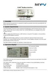
My-PV ELWA Manual


Læs gratis den danske manual til My-PV ELWA (4 sider) i kategorien Kedler & kedler. Denne vejledning er vurderet som hjælpsom af 6 personer og har en gennemsnitlig bedømmelse på 4.4 stjerner ud af 3.5 anmeldelser. Har du et spørgsmål om My-PV ELWA, eller vil du spørge andre brugere om produktet?

Side 1/4
ELWA
®
Modbus Interface Operation Manual, 171018
ELWA
®
Modbus Interface
Operation Manual
1. Assembly
Before placing into operation it is essential to read the assembly instructions provided with the
device and the ELWA manual.
2. System requirements
The ELWA Modbus Interface can be used with all ELWA devices with firmware Version 1.30 or
higher. Devices with serial numbers lower than 120100160810xxxx are equipped with earlier
firmware versions.
To update the ELWA firmware a USB Interface is required. The update is not possible by
using the ELWA Modbus Interface.
If the ELWA Modbus Interface is used in combination with the Smart-Home System
LOXONE, the "Loxone RS485 Interface" and not the "Loxone Modbus Interface" has to be used,
otherwise Bus conflicts may occur.
The latest software packages are available at www.my-pv.com.
3. Operation displays
The 3 LEDs on the top are the operation displays on ELWA. Functions are described in the ELWA
instruction manual.
The 3 green LEDs underneath show the operation condition of the ELWA Modbus Interface:
No LED light: no power supply
all 3 LED blinking: no connection to the ELWA
upper LED light: connection to the ELWA ok
middle LED light: Modbus order received (timeout approx. 5 sec)
LED operation display
Green (on ELWA)
Yellow (on ELWA)
Red (on ELWA)
green
green
green
ELWA
®
Modbus Interface Operation Manual, 171018
A proper communication between ELWA und ELWA Modbus Interface is only possible with
exact positioning (see assembly instructions).
4. Pins
Power supply Either with the provided power supply unit via Micro USB interface
(5VDC) or with 12-24V DC at the two pins +24V/GND
Temperature sensor Connect the provided temperature sensor at the two „Temp“ pins.
Polarity does not matter.
Modbus Connect the Modbus at the pins A D+ and B D-.
Consider polarity!
5. Functionality
The ELWA Modbus Interface is a link between the ELWA and a Modbus based bus system.
Because of the bus capability the allocation of bus addresses is required when there are
multiple devices in operation (register 1030).
The bus address is saved in the interface, not in the ELWA.
Furthermore the interface can control the hot water securing of ELWA by the provided
temperature sensor. For this purpose the following settings have to be made:
The hot water securing (Boost) even is operative without an active Modbus.
Assuming that the additional temperature sensor in the boiler is positioned higher than the
ELWA, it is recommended to set the boost-temperature on the interface (register 1009) a little
higher (e.g. 70 °C). Thereby the ELWA-internal control for hot water securing can be
circumvented.
The ELWA-internal control of the boost-time needs also to be adjusted. The corresponding entry
(register 1020) has to be set to 1441.


Produkt Specifikationer

Mærke: My-PV
Kategori: Kedler & kedler
Model: ELWA

Har du brug for hjælp?

Hvis du har brug for hjælp til My-PV ELWA stil et spørgsmål nedenfor, og andre brugere vil svare dig


Kedler & kedler My-PV Manualer

My-PV

My-PV ELWA Manual

24 August 2024
My-PV

My-PV AC-THOR Manual

24 August 2024

Kedler & kedler Manualer

Nyeste Kedler & kedler Manualer