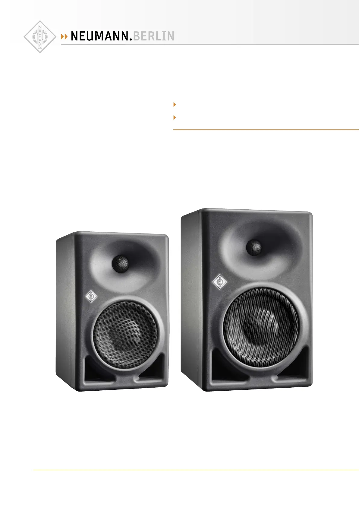
Neumann KH 870 Manual
Læs gratis den danske manual til Neumann KH 870 (39 sider) i kategorien Øreprop. Denne vejledning er vurderet som hjælpsom af 13 personer og har en gennemsnitlig bedømmelse på 4.6 stjerner ud af 7 anmeldelser.
Har du et spørgsmål om Neumann KH 870, eller vil du spørge andre brugere om produktet?
Produkt Specifikationer
| Mærke: | Neumann |
| Kategori: | Øreprop |
| Model: | KH 870 |
Har du brug for hjælp?
Hvis du har brug for hjælp til Neumann KH 870 stil et spørgsmål nedenfor, og andre brugere vil svare dig
Øreprop Neumann Manualer

Øreprop Manualer
- MusicMan
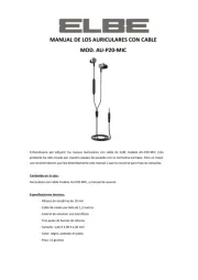
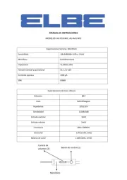
- Elbe
- Prixton
- Imperial
- Sencor
- JAZ Audio
- Denon
- Vocopro
- Belkin
- BlueAnt
- Fischer Amps
- Galaxy Audio
- Logitech
- Urbanista
- JLab
Nyeste Øreprop Manualer