Platinum T129K1 Manual

| Mærke: | Platinum |
| Kategori: | Kabler til pc'er og periferiudstyr |
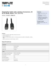
| Model: | T129K1 |
| Produktfarve: | Rød |
| Skærmtype: | LCD |
| Pakkevægt: | 256 g |
| Pakkebredde: | 71 mm |
| Pakkehøjde: | 163 mm |
| Opbevaringstemperatur (T-T): | -20 - 60 °C |
| Relativ luftfugtighed ved drift (H-H): | 10 - 90 % |
| Driftstemperatur (T-T): | 0 - 50 °C |
| Kabler inkluderet: | BNC, LAN (RJ-45) |
| Driftsspænding: | 55 V |
| Pakkelængde: | 36 mm |
| Understøttede stik: | BNC, RJ-11, RJ-12, RJ-45 |
Har du brug for hjælp?
Hvis du har brug for hjælp til Platinum T129K1 stil et spørgsmål nedenfor, og andre brugere vil svare dig
Kabler til pc'er og periferiudstyr Platinum Manualer

10 August 2024

9 August 2024

8 August 2024
Kabler til pc'er og periferiudstyr Manualer
- NewStar
- Aluratek
- TP-Link
- Intellinet
- Targus
- Sonero
- Opticis
- Hobbes
- Scosche
- AudioControl
- Inno-Hit
- Hamlet
- Brennenstuhl
- V7
- Nexibo
Nyeste Kabler til pc'er og periferiudstyr Manualer
3 April 2025

2 April 2025

2 April 2025

2 April 2025

2 April 2025

2 April 2025

2 April 2025

2 April 2025
1 April 2025
19 Marts 2025