Please read this manual thoroughly before installing and
operating your Inverter. This manual contains information
you need to obtain the performance required for your
application. Keep this manual for future reference.
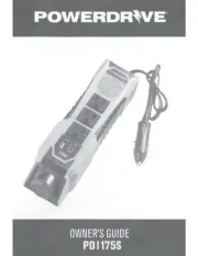
The PowerDrive" Bluetooth" inverter is the first
of
its kind
in the market! This inverter has high startin~ capability and
max efficiency
up
to
90%.
This Bluetooth" inverter can
connect with all Andriod" and iOS" smartphones. Our
phone
APP
can help check and keep you updated on the
battery voltage, output power and product temperature.
Set
up
the protections such as under voltage, over voltage,
overload and over-temperature at a distance! Also
included are personal settings and battery testing with a
more user friendly experience. Welcome to the future
of
power inverters!
WARNINGS,
CAUTIONS
AND
NOTES
It's very important that any operator and installer
of
this
inverter read and follow all WARNINGS, CAUTIONS AND
NOTES and all installation and operation instructions. In
particular, comply with
WARNINGS
(possibility
of
serious
injury or death),
CAUTIONS
(possibility
of
damage to the
inverter and/or other equipment), and
NOTES
(included to
assist you in achieving the maximum performance and
longest working life from this advanced-design inverter).
WARNINGS:
INVERTER
OUTPUT
This heavy-duty device produces voltages similar to
commercial AC power.
• Danger of shock or electrocution - treat inverter output
the same as commercial
AC
power.
• Do not use the inverter near flammable materials or in
any locations that may accumulate flammable fumes
or
gases. This is an electrical device that can briefly
spark when electrical connections are made or broken.
• Do
not
allow water or other liquids to contact the inverter.
• Do
not
use appliances with damaged
or
wet cords.
l1
•
Do
not connect to transfer switch.
•
Do
not connect to household outlets.
CAUTIONS:
INVERTER
OPERATING
ENYIROMENT
• Surrounding air temperature should be between
-4°F-104°F
-ideally
between 32°F-104°F.
• Keep the inverter away from direct sunlight,
if
at all
possible. Keep the area surrounding the inverter clear to
ensure free air circulation around the unit. Do not place
items on or over the inverter during operation. The unit
will shut down if the internal temperature gets too hot.
Restart the inverter after it cools.
• Your inverter will only operate from a 12V power source.
Do
not attempt to connect the inverter to any other power
source, including any
AC
power source. Do not reverse
the
DC
input
polarity-
this will void the warranty.
APPLIANCE
CAUTIONS
•
DO
NOT plug in battery chargers for cordless power tools
if the charger carries a warning that dangerous voltages
are present at the battery terminals.
• Certain chargers for small nickel-cadmium
or
nickel-
metal-hydride batteries can be damaged
if
powered by
this inverter. Two types
of
appliances are susceptible to
damage: Small, battery-operated appliances such as
flashlights, cordless razors and toothbrushes that plug
directly into an
AC
receptacle.
• Some fans with synchronous motors may slightly
increase in speed (RPM) when powered
by
the inverter.
This is not harmful to the fan
or
to
the inverter.
• Use safety approved
eX1ension
cords rated at
15 Amps or higher.
• GFCI devices may not work with modified sine wave
(MSW) power.
• This inverter is not tested for use with medical equipment.
•
Do
not use power strips with surge protection.
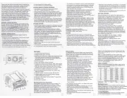
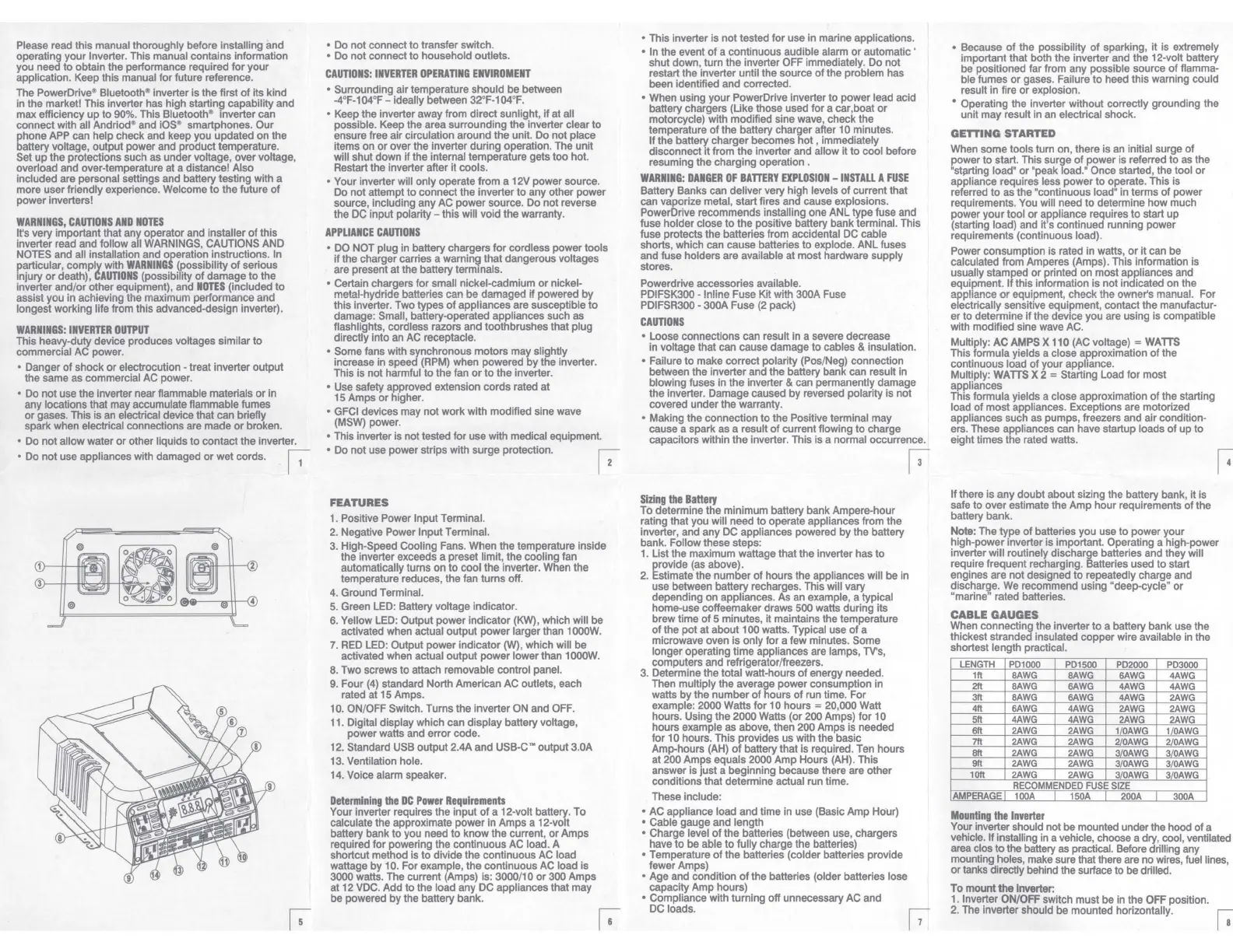
FEATURES
1. Positive Power Input Terminal.
2.
Negative Power Input Terminal.
3.
High-Speed Cooling Fans. When the temperature inside
the inverter exceeds a preset limit, the cooling fan
automatically turns on to cool the inverter. When the
temperature reduces, the fan turns off.
4.
Ground Terminal.
5.
Green LED: Battery voltage indicator.
6. Yellow LED: Output power indicator
(KW),
which will be
activated when actual output power larger than 1000W.
7.
RED
LED: Output power indicator
CN),
which will be
activated when actual output power lower than 1000W.
8. Two screws to attach removable control panel.
9.
Four
(4)
standard North American AC outlets, each
rated at
15
Amps.
10. ON/OFF Switch. Turns the inverter
ON
and OFF.
11. Digital display which can display battery voltage,
power watts and error code.
12. Standard USB output 2.4A and USB-C'" output 3.0A
13. Ventilation hole.
14. Voice alarm speaker.
Determining
the
DC
Power
Requirements
Your inverter requires the input
of
a 12-volt battery. To
calculate the approximate power in Amps a 12-volt
battery bank to you need to know the current,
or
Amps
required for powering the continuous AC load. A
shortcut method is to divide the continuous AC load
wattage
by
10. For example, the continuous
AC
load is
3000 watts. The current (Amps) is: 3000/10 or 300 Amps
at 12 VDC. Add to the load any DC appliances that may
be powered by the battery bank.
• This inverter is not tested for use in marine applications.
• In the event
of
a continuous audible alarm
or
automatic '
shut down, turn
the
inverter OFF immediately. Do not
restart the inverter until the source
of
the problem has
been identified and corrected.
• When using your PowerDrive inverter to power lead acid
battery chargers (Like those used for a car,boat
or
motorcycle) with modified sine wave, check the
temperature
of
the battery charger after 1 O minutes.
If the battery charger becomes hot , immediately
disconnect
it
from the inverter and allow it to cool before
resuming the charging operation .
WARNING:
DANGER
OF
BATTERY
EXPLOSION
-
INSTALL
A
FUSE
Battery Banks can deliver very high levels
of
current that
can vaporize metal, start fires and cause explosions.
PowerDrive recommends installing one ANL type fuse and
fuse holder close to
the
positive battery bank terminal. This
fuse protects the batteries from accidental DC cable
shorts, which can cause batteries to explode. ANL fuses
and fuse holders are available at most hardware supply
stores.
Powerdrive accessories available.
PDIFSK300 - lnline Fuse Kit with 300A Fuse
PDIFSR300 • 300A Fuse
(2
pack)
CAUTIONS
• Loose connections can result in a severe decrease
in voltage that can cause damage to cables & insulation.
• Failure to make correct polarity (Pos/Neg) connection
between the inverter and the battery bank can result
in
blowing fuses in the inverter & can permanently damage
the inverter. Damage caused by reversed polarity is not
covered under the warranty.
• Making the connection to the Positive terminal may
cause a spark as a result
of
current flowing to charge
capacitors within the inverter. This is a normal occurrence.
Sizing
the
Battery
To determine the minimum battery bank Ampere-hour
rating that you will need to operate appliances from the
inverter, and any DC appliances powered by the battery
bank. Follow these steps:
1. List the maximum wattage that the inverter has to
provide (as above).
2. Estimate the number of hours the appliances will be
in
use between battery recharges. This will vary
depending on appliances. As an example, a typical
home-use coffeemaker draws 500 watts during its
brew time
of
5 minutes, it maintains the temperature
of
the pot at about 100 watts. Typical use
of
a
microwave oven is only for a few minutes. Some
longer operating time appliances are lamps, TV's,
computers and refrigerator/freezers.
3. Determine the total watt-hours
of
energy needed.
Then multiply the average power consumption in
watts by the number
of
hours
of
run time. For
example: 2000 Watts for 10 hours = 20,000 Watt
hours. Using the 2000 Watts (or 200 Amps) for
to
hours example as above, then 200 Amps is needed
for 1 O hours. This provides us with the basic
Amp-hours (AH)
of
battery that is required. Ten hours
at 200 Amps equals 2000 Amp Hours (AH). This
answer is just a beginning because there are other
conditions that determine actual run time.
These include:
• AC appliance load and time in use (Basic Amp Hour)
• Cable gauge and length
• Charge level
of
the batteries (between use, chargers
have to be able to fully charge the batteries)
• Temperature
of
the batteries (colder batteries provide
fewer Amps)
• Age and condition
of
the batteries (older batteries lose
capacity Amp hours)
• Compliance with turning off unnecessary AC and
DC loads.
13
• Because
of
the possibility
of
sparking, it is
eX1remely
important that both the inverter and the 12-volt battery
be positioned far from any possible source
of
flamma-
ble fumes
or
gases. Failure
to
heed this warning could
result in fire or explosion.
• Operating the inverter without correctly grounding the
unit may result in an electrical shock.
GETIING
STARTED
When some tools turn on, there is an initial surge
of
power to start. This surge
of
power is referred to as the
'starting
load'
or "peak load.' Once started, the tool
or
appliance requires less power to operate. This is
referred to as the "continuous load" in terms
of
power
requirements. You will need to determine how much
power your tool or appliance requires to start up
(starting load) and it's continued running power
requirements (continuous load).
Power consumption is rated in watts,
or
it can be
calculated from Amperes (Amps). This information is
usually stamped or printed on most appliances and
equipment. If this information is not indicated on the
appliance
or
equipment, check the owner's manual. For
electrically sensitive equipment, contact the manufactur-
er to determine
if
the device you are using is compatible
with modified sine wave AC.
Multiply:
AC
AMPS
X 110
(AC
voltage) =
WATTS
This formula yields a close approximation
of
the
continuous load of your appliance.
Multiply:
WATTS
X 2 = Starting Load for most
appliances
This formula yields a close approximation
of
the starting
load
of
most appliances. Exceptions are motorized
appliances such
as
pumps, freezers and air condition-
ers. These appliances can have startup loads
of
up to
eight times the rated watts.
If there is any doubt about sizing the battery bank, it is
safe to over estimate the Amp hour requirements
of
the
battery bank.
Note:
The type
of
batteries you use to power your
high-power inverter is important. Operating a high-power
inverter will routinely discharge batteries and they will
require frequent recharging. Batteries used to start
engines are not designed to repeatedly charge and
discharge.
We
recommend using "deep-cycle" or
"marine" rated batteries.
CABLE GAUGES
When connecting the inverter to a battery bank use the
thickest stranded insulated copper
wire
available in the
shortest length practical.
LENGTH
PD1000 PD1500
PD2000
PD3000
1ft
BAWG BAWG
6AWG
4AWG
2ft
BAWG
6AWG
4AWG
4AWG
3ft
BAWG
6AWG
4AWG
2AWG
4ft
6AWG
4AWG
2AWG
2AWG
5ft
4AWG 4AWG
2AWG
2AWG
6ft
2AWG 2AWG
11
0AWG
1/
0AWG
7ft
2AWG 2AWG
2/0AWG
2/
0AWG
8ft
2AWG
2AWG
3I0AWG
3/
0AWG
9ft
2AWG 2AWG
3/0AWG
3/
0AWG
10ft
2AWG 2AWG
3/0AWG
3/
0AWG
RECOMMENDED
FUSE
SIZE
AMPERAGE
100A
150A
200A
I
300A
Mounting
the
Inverter
Your inverter should not be mounted under the hood of a
vehicle. If installing in a vehicle, choose a dry, cool, ventilated
area clos
to
the battery as practical. Before drilling any
mounting holes, make sure that there are no wires, fuel lines,
or tanks directly behind the surface to be drilled.
To mount the
Inverter:
1.
Inverter
ON/OFF
switch must be in the OFF position.
2.
The inverter should be mounted horizontally.