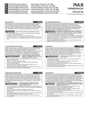
PISA11 Instruction Manual
PISA11 Bedienungsanleitung
Technical Data 1) Technische Daten 1) PISA11.401 PISA11.403 PISA11.404PISA11.402
Rated Voltage Nennspannung nom. DC 24V DC 24V DC 24V DC 24V
Input Voltage Range Eingangsspannungsbereich 18-30Vdc 18-30Vdc 18-30Vdc 18-30Vdc
Maximum Input Voltage
2) Maximale Eingangsspannung 2) max. 30Vdc 30Vdc 30Vdc 30Vdc
Input current Eingangsstrom nom. 4A 8A 12A 16A
Required Input Voltage for Turning-on of
Outputs
Erforderliche Eingangsspannung zum
Einschalten der Ausgänge
typ. 21.4Vdc 21.4Vdc 21.4Vdc 21.4Vdc
Turn-on Delay of Outputs 14) Einschaltverzögerung der Ausgänge 14) typ. 270ms 270ms 270ms 270ms
Outputs meets NEC-CLASS-2 Ausgänge erfüllen NEC-CLASS-2 Yes / Ja Yes / Ja No / Nein No / Nein
Input Voltage Protection Level
3) Aktivierung der Eingangsschutzschaltung 3) min. / max. 21.0Vdc / 21.8Vdc 21.0Vdc / 21.8Vdc 21.0Vdc / 21.8Vdc 21.0Vdc / 21.8Vdc
Output Current Channel 1
Channel 2
Channel 3
Channel 4
Ausgangsstrom Kanal 1
Kanal 2
Kanal 3
Kanal 4
nom.
nom.
nom.
nom.
1A
1A
1A
1A
2A
2A
2A
2A
3A
3A
3A
3A
4A
4A
4A
4A
Total Output Current (all 4 channels) Gesamter Ausgangsstrom (alle 4 Kanäle) nom. 4A 8A 12A 16A
Output Current Limitation 12) Ausgangsstrombegrenzung 12) min. / max. 9A / 12.7A 9A / 12.7A 16.6A / 23.6A 16.6A / 23.6A
Shutdown Times 13) at 2x rated current Abschaltzeiten 13) bei 2x Nennstrom typ. 1s at 2A 1s at 4A 1s at 6A 1s at 8A
at short circuit bei Kurzschluss typ. 110ms 110ms 10ms 10ms
Voltage Drop between Input and Output
4) Spannungsabfall zwischen Ein- und Ausgang
4) typ. 41mV 83mV 75mV 101mV
Stand-by Current Ruhestrom typ. 43mA 43mA 43mA 43mA
Power Losses in Stand-by Mode Verlustleistung im Leerlauf typ. 1.0W 1.0W 1.0W 1.0W
Power Losses at typical Output Loads
4) Verlustleistung bei typ. Ausgangsströmen
4) typ. 1.0W 1.3W 1.4W 1.8W
Max. Load Capacitors 5) per channel Max. Lastkapazität
5) pro Kanal 48mF / 41mF 94mF / 43mF 69mF / 22mF 57mF / 11mF
four outputs total alle 4 Ausgänge zusammen typ. / min. 135mF / 94mF 124mF / 43mF 69mF / 22mF 57mF / 11mF
Max. Load Capacitors 6) per channel Max. Lastkapazität 6) pro Kanal typ. / min. 49mF / 41mF 92mF / 73mF 80mF / 49mF 71mF / 45mF
Minimum Wire Gauge 8) Kleinster Kabelquerschnitt
8) min. 0.14mm20.25mm2 0.34mm20.5mm2
Degree of Pollution (non-conductive) Verschmutzungsgrad (nicht leitend) EN 50178 / 62103 2 2 2 2
Degree of Protection Schutzart EN 60529 IP20 IP20 IP20 IP20
Class of Protection Schutzklasse IEC 61140 III III III III
Reverse Polarity Protection (Input) Verpolschutz am Eingang No / Nein No / Nein No / Nein No / Nein
Return Voltage Resistance 9)
Rückspeisefestigkeit 9) max. 30Vdc 30Vdc 30Vdc 30Vdc
Parallel Use of Outputs Parallelschaltung von Ausgängen No / Nein No / Nein No / Nein No / Nein
Operational Temperature Range Betriebstemperaturbereich nom. -25°C - +70°C -25°C - +70°C -25°C - +70°C -25°C - +70°C
7)
Storage Temperature Range Lagertemperaturbereich nom. -40°C - +85°C -40°C - +85°C -40°C - +85°C -40°C - +85°C
Humidity 10) Feuchte 10) IEC 60068-2-30 5 - 95% r.H. 5 - 95% r.H. 5 - 95% r.H. 5 - 95% r.H.
Vibration Schwingen IEC 60068-2-6 2g 2g 2g 2g
Shock Schocken IEC 60068-2-27 30g 6ms, 20g 11ms 30g 6ms, 20g 11ms 30g 6ms, 20g 11ms 30g 6ms, 20g 11ms
Dimensions 11) (WxHxD) Abmessungen 11) (BxHxT) nom. 45 x 75 x 91mm 45 x 75 x 91mm 45 x 75 x 91mm 45 x 75 x 91mm
Weight Gewicht max. 120g, 0.26lb 120g, 0.26lb 120g, 0.26lb 120g, 0.26lb
Limited Warranty Gewährleistung Years / Jahre 3 3 3 3
1) All parameters are specified at 24Vdc, 25°C ambient temperature and after a 5 minutes run-in
time unless otherwise noted.
2) Absolute maximum continuous input voltage with no damage to the protection module.
3) Once the voltage tries to fall below this value, a protection circuit limits or shutdown the outputs in
order to maintain sufficient supply voltage. Voltage dips below this value can occur up to 200µs.
4) Typical value when all output channels are loaded with 50% of its nominal current.
5) Permissible capacitor, which can be connected to the outputs without shutdown of the protection
module. The listed values are valid for the entire temperature range.
Parameters for typical values Parameters for minimum values
PISA11.401 0.5A resistive load per output 1A constant current load per output
PISA11.402 1A resistive load per output 2A constant current load per output
PISA11.403 1.5A resistive load per output 3A constant current load per output
PISA11.404 2A resistive load per output 4A constant current load per output
6) Permissible capacitor, which can be connected to one particular output when only this output is
loaded and all others are not. The listed values are valid for the entire temperature range.
Parameters for typical values Parameters for minimum values
PISA11.401 with additional 0.5A resistive load with additional 1A constant current load
PISA11.402 with additional 1A resistive load with additional 2A constant current load
PISA11.403 with additional 1.5A resistive load with additional 3A constant current load
PISA11.404 with additional 2A resistive load with additional 4A constant current load
7) De-rate output current linearly from 20A to 15A (sum of all output currents) between 60°C and
70°C. De-rate the output current equally between the individual outputs.
8) For a typical installation in accordance with VDE 0891 and VDE 0100-523 for 30°C ambient
temperature.
9) Loads such as decelerating motors and inductors can feed voltage back to the output of the PISA
module. The figure represents the maximum allowed feed-back voltage.
10) Do not energize while condensation is present.
11) Depth without DIN-rail and signal connector. Add 13mm in depth for the signal connector if
needed.
12) Provided that the supplying power source can deliver enough current. This current can be drawn
from each individual output for a short period of time regardless whether it is a 1A, 2A, 3A or 4A
output. According to the specified ampacity of the outputs, the current can flow for a shorter or
longer period of time before the protection module shutdown all four outputs at the same time.
13) The “timer” for the shutdown starts immediately once the nominal current levels are exceeded. All
output channels will shutdown, if one channel is overloaded. See Fig. 5 for more values.
14) All outputs turn on at the same time.
1) Alle Werte gelten bei 24Vdc, 25°C Umgebungstemperatur und nach einer Aufwärmzeit von 5
Minuten, wenn nichts anderes angegeben ist.
2) Absolute Obergrenze, bei der das Sicherungsmodul noch nicht zerstört wird.
3) Unterhalb dieser Eingangsspannung wird die Schutzschaltung aktiviert (verzögert um 200µs),
um einen Einbruch der Versorgungsspannung zu vermeiden. Die Ausgangsströme werden
für eine bestimmte Zeit begrenzt und danach abgeschaltet.
4) Typischer Wert, wenn alle Ausgänge mit 50% des Nennstroms belastet werden.
5) Zulässige Gesamtkapazität, die an den vier Ausgängen zugeschaltet werden kann, ohne
Abschaltung des Moduls. Die Werte gelten für den gesamten Temperaturbereich.
Parameter für typische Werte Parameter für Minimumwerte
PISA11.401 0,5A Widerstandslast pro Ausgang 1A Konstantstromlast pro Ausgang
PISA11.402 1A Widerstandslast pro Ausgang 2A Konstantstromlast pro Ausgang
PISA11.403 1,5A Widerstandslast pro Ausgang 3A Konstantstromlast pro Ausgang
PISA11.404 2A Widerstandslast pro Ausgang 4A Konstantstromlast pro Ausgang
6) Zulässige Kapazität, die an einem Ausgang zugeschaltet werden kann, wenn alle anderen
Ausgänge unbelastet sind. Die Werte gelten für den gesamten Temperaturbereich.
Parameter für typische Werte Parameter für Minimumwerte
PISA11.401 mit zusätzlich 0,5A Widerstandslast mit zusätzlich 1A Konstantstromlast
PISA11.402 mit zusätzlich 1A Widerstandslast mit zusätzlich 2A Konstantstromlast
PISA11.403 mit zusätzlich 1,5A Widerstandslast mit zusätzlich 3A Konstantstromlast
PISA11.404 mit zusätzlich 2A Widerstandslast mit zusätzlich 4A Konstantstromlast
7) Zwischen +60°C und +70°C ist eine lineare Stromrücknahme von 20A nach 15A erforderlich.
Gleichmäßige Stromrücknahme zwischen allen Ausgängen erforderlich.
8) Für eine typische Installation nach VDE 0891 und VDE 0100-523 bei 30°C Umgebung.
9) Bremsende Motoren oder Induktivitäten können Spannung zum Ausgang des PISA Moduls
rückspeisen. Der Wert gibt die maximal zulässige Rückspeisespannung an.
10) Nicht betreiben, solange das Gerät Kondensation aufweist.
11) Tiefe ohne DIN-Schiene und Signalstecker. Zusätzlich 13mm in der Tiefe für Signalstecker,
wenn benötigt.
12) Vorausgesetzt, die speisende Stromversorgung kann genügend Strom liefern. Dieser Strom
kann kurzzeitig aus jedem einzelnen Ausgangskanal entnommen werden, unabhängig, ob es
ein 1A-, 2A-, 3A- oder 4A-Ausgang ist. Je nach Nennstrom des Ausgangskanals kann dieser
Strom kürzer oder länger fließen bis eine Abschaltung aller vier Ausgänge erfolgt.
13) Der „Timer“ zur Abschaltung startet bei Überschreitung des Nennstroms. Bei Überlast an
einem Kanal werden alle Kanäle abgeschaltet. Siehe auch Bild 5 für weitere Werte.
14) Alle Ausgänge schalten gleichzeitig ein.