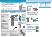
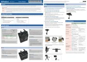
Roland R-44 Manual
Roland
Ikke kategoriseret
R-44
Læs gratis den danske manual til Roland R-44 (92 sider) i kategorien Ikke kategoriseret. Denne vejledning er vurderet som hjælpsom af 11 personer og har en gennemsnitlig bedømmelse på 4.7 stjerner ud af 6 anmeldelser. Har du et spørgsmål om Roland R-44, eller vil du spørge andre brugere om produktet?
Side 1/92


2
204
* Microsoft and Windows are registered trademarks of Microsoft Corporation.
206j
*Windows
®
is known officially as: “Microsoft
®
Windows
®
operating system.”
207
* Apple and Macintosh are registered trademarks of Apple Inc.
209
* Mac OS is a trademark of Apple Inc.
220
* All product names mentioned in this document are trademarks or registered trademarks of their respective owners.
239
* The SD logo ( ) and SDHC logo ( ) are trademarks of SD-3C, LLC.
236
* Fugue © 1999–2013 Kyoto Software Research, Inc. All rights reserved.
fig.Fugue-logo.eps
240
* MMP (Moore Microprocessor Portfolio) refers to a patent portfolio concerned with microprocessor architecture, which
was developed by Technology Properties Limited (TPL). Roland has licensed this technology from the TPL Group.
IMPORTANT: THE WIRES IN THIS MAINS LEAD ARE COLOURED IN ACCORDANCE WITH THE FOLLOWING CODE.
BLUE:
BROWN:
As the colours of the wires in the mains lead of this apparatus may not correspond with the coloured markings identifying the
terminals in your plug, proceed as follows:
The wire which is coloured BLUE must be connected to the terminal which is marked with the letter N or coloured BLACK.
The wire which is coloured BROWN must be connected to the terminal which is marked with the letter L or coloured RED.
Under no circumstances must either of the above wires be connected to the earth terminal of a three pin plug.
NEUTRAL
LIVE
For the U.K.
For the USA
DECLARATION OF CONFORMITY
Compliance Information Statement
Model Name :
Type of Equipment :
Responsible Party :
Address :
Telephone :
R-44E
Portable Recorder
Roland Systems Group U.S.
5100 S. Eastern Avenue, Los Angeles, CA 90040-2938
(323) 890-3700

3
USING THE UNIT SAFELY
Used for instructions intended to alert the
user to the risk of injury or material
damage should the unit be used
improperly.
* Material damage refers to damage or
other adverse effects caused with
respect to the home and all its
furnishings, as well to domestic animals
or pets.
Used for instructions intended to alert the
user to the risk of death or severe injury
should the unit be used improperly.
The symbol alerts the user to things that must be
carried out. The specific thing that must be done is
indicated by the design contained within the circle. In the
case of the symbol at left, it means that the power-cord
plug must be unplugged from the outlet.
The symbol alerts the user to important instructions or
warnings.The specific meaning of the symbol is
determined by the design contained within the triangle. In
the case of the symbol at left, it is used for general
cautions, warnings, or alerts to danger.
The symbol alerts the user to items that must never be
carried out (are forbidden). The specific thing that must
not be done is indicated by the design contained within
the circle. In the case of the symbol at left, it means that
the unit must never be disassembled.
About WARNING and CAUTION Notices
About the Symbols
ALWAYS OBSERVE THE FOLLOWING
WARNING WARNING WARNING
To completely turn o power to the unit,
pull out the plug from the outlet
Even with the power switch
turned o , this unit is not
completely separated from
its main source of power.
When the power needs to be
completely turned o , turn o the
power switch on the unit, then pull
out the plug from the outlet. For this
reason, the outlet into which you
choose to connect the power cord’s
plug should be one that is within easy
reach and readily accessible.
Concerning the Auto O function
The power to this unit will
be turned o automatically
after a predetermined
amount of time has passed
since it was last used for playing
music, or its buttons or controls were
operated (Auto O function). If you
do not want the power to be turned
o automatically, disengage the Auto
O function (p. 71).
Do not disassemble or modify by
yourself
Do not carry out anything
unless you are instructed to
do so in the owner’s manual.
Otherwise, you risk causing
malfunction.
Do not repair or replace parts by yourself
Refer all servicing to your
retailer, the nearest Roland
Service Center, or an
authorized Roland
distributor, as listed on the
“Information.”
Do not use or store in the following
types of locations
• Subject to temperature
extremes (e.g., direct
sunlight in an enclosed
vehicle, near a heating
duct, on top of heat-
generating equipment);
or are
• Damp (e.g., baths,
washrooms, on wet oors);
or are
• Exposed to steam or smoke; or are
• Subject to salt exposure; or are
• Exposed to rain; or are
• Dusty or sandy; or are
• Subject to high levels of vibration
and shakiness.
Do not place in an unstable location
Otherwise, you risk injury as
the result of the unit
toppling over or dropping
down.
Use only the supplied AC adaptor and
the correct voltage
Be sure to use only the AC
adaptor supplied with the
unit. Also, make sure the line
voltage at the installation
matches the input voltage
speci ed on the AC adaptor’s body.
Other AC adaptors may use a di erent
polarity, or be designed for a di erent
voltage, so their use could result in
damage, malfunction, or electric
shock.
Use only the supplied power cord
Use only the attached power
cord. Also, the supplied
power cord must not be
used with any other device.
Do not bend the power cord or place
heavy objects on it
Otherwise, re or electric
shock may result.
Avoid extended use at high volume
Use of the unit at high
volume for extended
periods of time may cause
hearing loss. If you ever
experience any hearing loss or ringing
in the ears, you should immediately
stop using the unit and consult a
specialized physician.

4
USING THE UNIT SAFELY
Do not allow foreign objects or liquids to
enter unit; never place containers with
liquid on unit
Do not place containers
containing liquid (e.g.,
ower vases) on this
product. Never allow foreign
objects (e.g., ammable
objects, coins, wires) or
liquids (e.g., water or juice)
to enter this product. Doing
so may cause short circuits, faulty
operation, or other malfunctions.
Turn o the unit if an abnormality or
malfunction occurs
Immediately turn the unit
o , remove the AC adaptor
from the outlet, and request
servicing by your retailer,
the nearest Roland Service Center, or
an authorized Roland distributor, as
listed on the “Information” when:
• The AC adaptor or the power cord
has been damaged; or
• If smoke or unusual odor occurs; or
• Objects have fallen into, or liquid
has been spilled onto the unit; or
• The unit has been exposed to rain
(or otherwise has become wet); or
• The unit does not appear to
operate normally or exhibits a
marked change in performance.
Be cautious to protect children from
injury
Always make sure that an
adult is on hand to provide
supervision and guidance
when using the unit in
places where children are present, or
when a child will be using the unit.
Do not drop or subject to strong impact
Otherwise, you risk causing
damage or malfunction.
Do not share an outlet with an
unreasonable number of other devices
Otherwise, you risk
overheating or re.
Do not use overseas
Before using the unit in
overseas, consult with your
retailer, the nearest Roland
Service Center, or an
authorized Roland distributor, as
listed on the “Information.”
Handle batteries carefully
If used improperly, you risk
the dangers of uid leakage,
overheating, combustion,
explosion, etc. Carefully
observe the following:
• Do not heat, disassemble,
or toss them into a re or
water.
• Do not expose them to
sunlight, ame, or any
other source of extreme
heat.
• Do not attempt to charge
a dry cell battery.
• When using a
rechargeable battery and
a charger, make sure to
use only the combination
of rechargeable battery
and charger that has
been speci ed by the
battery manufacturer.
Also, be sure to read all
of the precautions that
were supplied with the
rechargeable battery
and charger, and abide
by them when using the
battery/charger.
Handle lithium batteries carefully
• Lithium batteries must
never be recharged,
heated, taken apart, or
thrown into a re or water.
• Keep lithium batteries out
of reach of small children.
If a child has accidentally
swallowed a battery, see a
doctor immediately.
• Never expose lithium
batteries to excessive heat
such as sunshine, re or
the like.
CAUTION
Place in a well ventilated location
The unit and the AC adaptor
should be located so their
location or position does
not interfere with their
proper ventilation.
When disconnecting the power cord,
grasp it by the plug
To prevent conductor
damage, always grasp the
power cord by its plug when
disconnecting it from this
unit or from a power outlet.
Periodically clean the power plug
An accumulation of dust or
foreign objects between the
power plug and the power
outlet can lead to re or
electric shock.
At regular intervals, be sure to pull
out the power plug, and using a dry
cloth, wipe away any dust or foreign
objects that may have accumulated.
Disconnect the power plug whenever
the unit will not be used for an
extended period of time
Fire may result in the
unlikely event that a
breakdown occurs.
Route all power cords and cables in such
a way as to prevent them from getting
entangled
Injury could result if
someone were to trip on a
cable and cause the unit to
fall or topple.
Avoid climbing on top of the unit, or
placing heavy objects on it
Otherwise, you risk injury as
the result of the unit
toppling over or dropping
down.
Never connect/disconnect a power plug
if your hands are wet
Otherwise, you could
receive an electric shock.
WARNING WARNING

5
USING THE UNIT SAFELY
Disconnect all cords/cables before
moving the unit
Before moving the unit,
disconnect the power plug
from the outlet, and pull out
all cords from external
devices.
Before cleaning the unit, disconnect the
power plug from the outlet
If the power plug is not
removed from the outlet,
you risk receiving an electric
shock.
Whenever there is a threat of lightning,
disconnect the power plug from the
outlet
If the power plug is not
removed from the outlet,
you risk receiving an electric
shock.
Handle batteries carefully
If used improperly, batteries
may explode or leak and
cause damage or injury. In
the interest of safety, please
read and observe the
following precautions.
• Carefully follow the
installation instructions for
batteries, and make sure
you observe the correct
polarity.
• Avoid using new batteries
together with used ones.
In addition, avoid mixing
di erent types of batteries.
• Remove the batteries whenever
the unit is to remain unused for an
extended period of time.
• Never keep batteries together with
metallic objects such as ballpoint
pens, necklaces, hairpins, etc.
• Used batteries must be disposed
of in compliance with whatever
regulations for their safe disposal
that may be observed in the region
in which you live.
Handle the ground terminal carefully
If you remove the screw
from the ground terminal,
be sure to replace it; don’t
leave it lying around where
it could accidently be swallowed by
small children. When refastening the
screw, make that it is rmly fastened,
so it won’t come loose.
Precautions concerning use of phantom
power supply
Always turn the phantom
power o when connecting
any device other than
condenser microphones
that require phantom power. You risk
causing damage if you mistakenly
supply phantom power to dynamic
microphones, audio playback devices,
or other devices that don’t require
such power. Be sure to check the
speci cations of any microphone you
intend to use by referring to the
manual that came with it.
This instrument’s phantom power:
48 V DC, 8 mA Max
(Total of all channels must be 20 mA
or less)
Take care not to get burned
Batteries may reach a high
temperature; please be
careful to avoid burning
yourself.
Handle leaking batteries carefully
• Do not touch the liquid
with your bare hands.
• If any of the leaking uid
gets into your eyes, the
loss of vision may result.
Do not rub your eyes;
use clean water to ush
them thoroughly. Then,
promptly see a doctor.
• Burning of the skin or dermatitis
may result if uid has gotten
onto your skin or clothing. Use
clean water to ush a ected areas
thoroughly; then, promptly see a
doctor.
• Using a soft cloth, carefully wipe
any remaining uid from the inside
of the battery compartment. Then,
install new batteries.
CAUTION CAUTION

6
IMPORTANT NOTES
Power Supply
• Do not connect this unit to same
electrical outlet that is being used
by an electrical appliance that is
controlled by an inverter or a motor
(such as a refrigerator, washing
machine, microwave oven, or air
conditioner). Depending on the way
in which the electrical appliance is
used, power supply noise may cause
this unit to malfunction or may
produce audible noise. If it is not
practical to use a separate electrical
outlet, connect a power supply
noise lter between this unit and
the electrical outlet.
• The AC adaptor will begin to
generate heat after long hours of
consecutive use. This is normal, and
is not a cause for concern.
• The use of an AC adaptor is
recommended as the unit’s power
consumption is relatively high.
Should you prefer to use batteries,
please use the alkaline batteries or
rechargeable Ni-MH batteries.
• If the unit has been used with a
power supply that has not been
speci ed as suitable for the unit,
the subsequent performance and
operation of the unit can no longer
be guaranteed. Also note that we
may not be able to accept the unit
for servicing and repairs.
Power Supply: Use of Batteries
• Before installing/removing batteries,
make sure to turn o the power
to this unit and disconnect all
connections to other devices.
• If operating this unit on batteries,
please use the alkaline batteries or
rechargeable Ni-MH batteries.
Placement
• Using the unit near power ampli ers
(or other equipment containing
large power transformers) may
induce hum. To alleviate the
problem, change the orientation
of this unit; or move it farther away
from the source of interference.
• This unit may interfere with radio
and television reception. Do not
use this unit in the vicinity of such
receivers.
• Noise may be produced if wireless
communications devices, such as
cell phones, are operated in the
vicinity of this unit. Such noise could
occur when receiving or initiating
a call, or while conversing. Should
you experience such problems,
you should relocate such wireless
devices so they are at a greater
distance from this unit, or switch
them o .
• Do not expose the unit to direct
sunlight, place it near devices
that radiate heat, leave it inside
an enclosed vehicle, or otherwise
subject it to temperature extremes.
Excessive heat can deform or
discolor the unit.
• When moved from one location to
another where the temperature
and/or humidity is very di erent,
water droplets (condensation)
may form inside the unit. Damage
or malfunction may result if you
attempt to use the unit in this
condition. Therefore, before
using the unit, you must allow it
to stand for several hours, until
the condensation has completely
evaporated.
• Depending on the material and
temperature of the surface on which
you place the unit, its rubber feet
may discolor or mar the surface.
You can place a piece of felt or cloth
under the rubber feet to prevent
this from happening. If you do so,
please make sure that the unit will
not slip or move accidentally.
• Do not place containers or anything
else containing liquid on top of this
unit. Also, whenever any liquid has
been spilled on the surface of this
unit, be sure to promptly wipe it
away using a soft, dry cloth.
Maintenance
• For everyday cleaning wipe the unit
with a soft, dry cloth or one that
has been slightly dampened with
water. To remove stubborn dirt, use
a cloth impregnated with a mild,
non-abrasive detergent. Afterwards,
be sure to wipe the unit thoroughly
with a soft, dry cloth.
• Never use benzine, thinners, alcohol
or solvents of any kind, to avoid the
possibility of discoloration and/or
deformation.
Repairs and Data
• Before sending the unit away for
repairs, be sure to make a backup
of the data stored within it; or
you may prefer to write down the
needed information. Although we
will do our utmost to preserve the
data stored in your unit when we
carry out repairs, in some cases,
such as when the memory section
is physically damaged, restoration
of the stored content may be
impossible. Roland assumes no
liability concerning the restoration
of any stored content that has been
lost.
Additional Precautions
• Any data stored within the unit can
be lost as the result of equipment
failure, incorrect operation, etc.
To protect yourself against the
irretrievable loss of data, try to make
a habit of creating regular backups
of the data you’ve stored in the unit.
• Roland assumes no liability
concerning the restoration of any
stored content that has been lost.
• Use a reasonable amount of care
when using the unit’s buttons,
sliders, or other controls; and when
using its jacks and connectors.
Rough handling can lead to
malfunctions.
• Never strike or apply strong
pressure to the display.
• When disconnecting all cables,
grasp the connector itself—never
pull on the cable. This way you will
avoid causing shorts, or damage to
the cable’s internal elements.
• To avoid disturbing others nearby,
try to keep the unit’s volume at
reasonable levels.
• When you need to transport the
unit, pack it in shock-absorbent
material. Transporting the unit
without doing so can cause it to
become scratched or damaged, and
could lead to malfunction.
Using External Memories
• Please observe the following
precautions when handling external
memory devices.
Also, make sure to carefully observe
all the precautions that were
supplied with the external memory
device.
• Do not remove the device while
reading/writing is in progress.
• To prevent damage from static
electricity, discharge all static
electricity from your person
before handling the device.

7
Contents
USING THE UNIT SAFELY...............3
IMPORTANT NOTES ......................6
Checking the Included Items.........8
Introducing the R-44 ....................9
Names of Things and What They Do................ 9
Display................................................................. 18
Projects................................................................. 22
Getting Ready to Use the R-44 ...24
Connecting the AC Adaptor and Turning
the Power On/Off.............................................. 24
Installing Batteries and Turning on
the Power............................................................. 25
Preparing the SD Memory Card ...................... 28
Recording ..................................29
Recording from a Connected Microphone..... 29
Recording from the Internal Mics....................33
Recording Digital Audio from a
Digital Device ..................................................... 34
Simultaneously Recording Sound from
Connected Microphones and
a Digital Device .................................................. 35
Simultaneously Recording Sound from
Connected External Microphones and
the Internal Mics................................................. 37
Recording Digital Audio from
an Analog Device ............................................... 39
Simultaneously Recording Sound from
Connected Microphones and
an Analog Device ............................................... 40
Playing Back .............................42
Connections Before Playback ........................... 42
Connecting Headphones .................................42
Connecting Amplified Speakers.....................42
Connecting a Mixer or Other Analog
Device .................................................................42
Connecting a Device Having
a Digital Input Port...........................................43
Setup Before Playback ....................................... 44
Player Setup.......................................................44
Speaker Settings ................................................45
Playing Back........................................................ 46
Normal Playback ..............................................46
Markers ..............................................................47
Repeat Playback (A-B REPEAT).....................48
Specifying the Project Playback Order
(Playlist Function).............................................49
Manipulating a Project (Finder).. 50
Selecting a Project (Select) ................................ 50
Renaming a Project (Rename).......................... 51
Copying a Project (Copy) ................................. 52
Moving a Project (Move) .................................. 53
Deleting a Project (Delete) ................................ 54
Creating a New Folder (Make Folder)............ 55
Repairing a Project (Repair) ............................. 56
Setting the Color of Sound
(Effects Settings) ........................ 57
Applying Effects ................................................ 58
Effects .................................................................. 60
System Setup ............................ 62
Example Operations.......................................... 63
Recording Setup................................................63
Date & Time Settings........................................64
Project Name Settings ......................................65
Formatting and Checking
the SD Memory Card .......................................66
Executing Factory Reset
(Restoring Factory Default Settings) ..............67
System Menu ...................................................... 68
Appendix .................................. 73
Connecting to a Computer ............................... 73
Connecting the R-44 to Your Computer........73
Disconnecting the R-44 from a Computer.....74
Remotely Linking Two Connected
R-44 Units............................................................ 75
Messages .................................. 76
Troubleshooting ........................ 77
Main Specifications.................... 81
Block Diagram .......................... 83
Index ........................................ 84
Before using this unit, carefully read the sections
entitled: “USING THE UNIT SAFELY” and
“IMPORTANT NOTES” (p. 3
–6). These sections
provide important information concerning the proper
operation of the unit. Additionally, in order to feel
assured that you have gained a good grasp of every
feature provided by your new unit, Owner’s Manual
should be read in its entirety. The manual should be
saved and kept on hand as a convenient reference.
Copyright © 2013 ROLAND CORPORATION
All rights reserved. No part of this publication may be reproduced in any form without the written permission
of ROLAND CORPORATION.
Roland is a registered trademark of Roland Corporation in the United States and/or other countries.

8
Checking the Included Items
The R-44 comes with the following items. Please check that all of these items are present after opening the
package. If any items are missing, please contact the retailer from whom you purchased the R-44.
■ R-44
■ AC Adaptor
This AC adaptor is designed specifically for the R-44. Do not attempt to use any other adaptor with the R-44.
■ USB Cable (mini B TYPE; 1 meter)
You can use this cable to connect the R-44 to the USB connector of your computer.
* If the AC adaptor or USB cable becomes damaged or if you need a replacement for any reason, please contact one of
the Service Centers listed in the “Information” section at the end of this manual.
* Don't remove the ferrite core that's attached to the USB cable.
■ Owner’s Manual
This is the document you’re reading. Keep it at hand for ready reference.

9
Introducing the R-44
fig.panel-1.eps
Internal Mics [MIC-L, MIC-R]
These stereo mics are built into the R-44. The audio entering MIC-L is recorded on the 1L channel, and the
audio from MIC-R is recorded on the 1R channel. If you are recording with the internal mics, set the System
Settings menu item Recording Setup to Int-Mic.
For details, refer to “Recording from the Internal Mics” (p. 33).
* Do not connect anything to input jacks that are not used.
Internal Speakers
These built-in speakers are for monitoring sound. If you want sound to be played from the internal speakers,
set the System Settings menu item Speaker to ON. For details, refer to “Speaker Settings” (p. 45).
* No sounds are played from the internal speakers if headphones are connected to the Headphone jack . Sound
is not played from the internal speakers while recording or in recording-standby mode to prevent acoustic feedback.
Names of Things and What They Do
Top Panel
1
2
4
3
5 6
7
8 9
10
2
1
13
11
12
14 15 16
17
1
2
25

10
Introducing the R-44
Phantom Power Switches [PHANTOM POWER]
These switches turn the phantom power on/off for the XLR connectors of the combo input jacks located on
the right panel. You can turn phantom power on/off separately for channels 1/2/3/4 because they have
separate switches.
* Always turn the phantom power off when connecting any device other than
condenser microphones that require phantom power. You risk causing damage
if you mistakenly supply phantom power to dynamic microphones, audio
playback devices, or other devices that do not require such power. Be sure to
check the specifications of any microphone you intend to use by referring to the
manual that came with it.
This instrument’s phantom power: 48 V DC, 8 mA Max (total of all channels must be 20 mA or less)
Hold Switch [HOLD]
By selecting the HOLD ON position, you can disable the panel buttons so that unwanted operations will not
occur if a button is pressed accidentally.
However, even if this switch is set to HOLD ON, the Phantom power switches , Low cut switch
, Limiter switch , Input level knobs , and Monitor level knob will still be operable.
Low Cut Switch [LOW CUT]
Turing this switch on allows you to record while cutting the lower range portion of the input signal. Turn
it on when breath noise (breathing sounds during voice recording) or wind noise (when recording outside)
may be a problem.
Limiter Switch [LIMITER]
This switch turns the input level limiter on/off.
The limiter compresses the input level appropriately to prevent distortion when the input level is too high.
The limiter can be set to work with respect to each channel independently or for a combination of channels
(linked). For details, refer to “Limiter link” (p. 70).
1
2
4
3
5 6
7
8 9
10
2
1
13
11
12
14 15 16
17
3
XLR plug
TRS phone
plug
(balanced)
Phone plug
(unbalanced)
4
3
5
6
23
24
5
6

11
Introducing the R-44
Power Switch [POWER]
This switch turns the power on/off. To turn the power on or off, press and hold the [POWER] switch for
about two seconds. The [POWER] switch is lit blue when the power is on.
* Do not turn off power to the R-44 in the following situations. The SD memory card may be damaged.
• When writing to or reading from the SD memory card, such as during recording or playback
If power is mistakenly turned off during recording, the recorded data may not be saved on the SD
memory card.
Note that pressing the power switch during recording will not turn off power.
• When “Now Processing!” or “Checking Card...” appears on the R-44’s display
• When connected to a PC
Effects Button [EFFECTS]
This button puts the R-44 in Effect mode, where you can make effect settings. When effects are operating,
the Effect button lights in orange.
For details, refer to “Setting the Color of Sound (Effects Settings)” (p. 57).
Exit Button [EXIT]
You use this button to return to the previous screen or to cancel an operation.
Scrub Dial [SCRUB/VALUE]
Use this dial to select a setting item or to change a value. You can also turn the scrub dial to move the current
location forward or backward when the R-44 is stopped or when playback is paused.
In the finder screen, the scrub dial can also be used to select songs.
Marker Buttons [CLEAR] [ ] [ ] [MARK] /
Cursor Buttons [ ] [ ] [ ] [ ]
When using as Marker buttons (p. 47)
Clear button [CLEAR]
This button deletes markers assigned with the [MARK] button. Markers are deleted successively,
starting at the marker located immediately before the current location.
Marker button [ ]
This button moves the position to the marker immediately before the current location (the previous
marker).
If the current playback location is before the first marker, pressing this button moves the position to the
beginning of the project. The position is also moved to the beginning of the project if no markers have
been set.
Marker button [ ]
This button moves the position to the marker immediately following the current location (the next
marker).
If the current playback location is at the last marker, pressing this button moves the position to the end
of the project. The position is also moved to the end of the project if no markers have been set.
Mark button [MARK]
You assign a marker to a desired location in the project file by pressing this button. Markers are
numbered sequentially from the beginning of the project.
When using as Cursor button
You use these buttons to select items shown in the display.
MENU Button [MENU]
This button puts the R-44 in different modes where you can make various settings.
For details, refer to “System Setup” (p. 62).
A-B Repeat Button [A-B REPEAT]
This button lets you repeatedly play the region between two points (A and B) in the project. Simply assign
marker A and marker B while the project is playing, and playback will repeat between markers A and B.
For details, refer to “Repeat Playback (A-B REPEAT)” (p. 48).
7
8
9
10
11
12
13

12
Introducing the R-44
PREV Button [PREV]
Pressing the [PREV] button while a project is playing or stopped returns the project to the beginning
(00:00:00:00). Pressing this button at the beginning of a project moves to the previous project.
You can also press and hold down this button to rewind. This feature is available both while playing and
while stopped.
*If Play Mode is set to Single in the Player Setup system setting, you cannot move to the previous or next project
during playback.
NEXT Button [NEXT]
Pressing the [NEXT] button jumps to the next project. You can also press and hold this button to fast-
forward. This feature is available both while playing and while stopped.
*If Play Mode is set to Single in the Player Setup system setting, you cannot move to the previous or next project
during playback.
Play Button [PLAY]
This button starts playback. The [PLAY] button is lit blue during playback.
Enter/Finder Button [ENTER/FINDER]
You use this button to confirm a setting or to set a value. You can also press this button to use the Finder
function. For more about the Finder function, refer to “Manipulating a Project (Finder)” (p. 50).
1
2
4
3
5 6
7
8 9
10
2
1
13
11
12
14 15 16
17
14
15
16
17

13
Introducing the R-44
fig.panel-2.eps
Display
The display shows information about the R-44’s status.
For details, refer to “Display” (p. 18).
Display Button [DISP]
This button switches the contents of the R-44’s display.
For details, refer to “Display” (p. 18).
Stop Button [STOP]
This button stops playback or recording. If you press the [STOP] button during playback, the timer
counter displays the time when you pressed the [STOP] button.
Pause Button [PAUSE]
This button pauses playback or recording. During recording, sound is still output even if paused.
Record Button [REC]
Recording will begin immediately when you press the [REC] button. The [REC] button is lit red during
recording. If you hold down the [PAUSE] button and press the [REC] button, the [REC] button will blink
red, and the R-44 enters recording standby mode. Recording will begin when you press the [REC] button
or [PAUSE] button .
Input Level Knobs 1–4 [LEVEL]/[SENS]
These knobs adjust the input level from each Combo input jack 1–4 (p. 30).
You can adjust sensitivity to 11 levels: +4, -2, -8, -14, -20, -26, -32, -38, -44, -50, and -56 dBu. You can also set
the level from negative infinity to +8 dB, with the central position at 0 dB.
* When using Internal mics , sensitivity can be set to one of three levels (Low, Mid, or Hi) and the level can
be set from negative infinity to +18 dB. Also, sensitivity for both MIC-L and MIC-R can be adjusted with Input
level knob 1. The level for MIC-L can be adjusted with Input level knob 1, and the level for MIC-R can be
adjusted with Input level knob 2.
Monitor Level Knob [MONITOR (PUSH) SELECT]
This knob adjusts the output volume from the Internal speakers and the Headphone jack .
This knob does not adjust the volume from the Line output jacks . If you want to adjust the volume
of the Line output jacks, adjust the controls of the external speakers or playback system connected to the
Line output jacks.
You can press the this knob from the main screen to select a channel to monitor.
For details, refer to “Display” (p. 18).
Headphone Jack [PHONES]
You can connect a set of headphones with this jack. Use the Monitor level knob to adjust the volume.
If you connect headphones, no sound is output from the Internal speakers .
Front Panel
18
19
20
21
22
23
25
24
18
19
20
21
22
21
23
35
34
1
24
2
25
33
25
24
2

14
Introducing the R-44
fig.panel-3.eps
Control Sync Connector [CTRL SYNC]
You can perform clock-synchronized recording of up to 8 channels by connecting two R-44 units with a
mini-type stereo cable via the CTRL SYNC connectors. You can also remotely link recording standby, start,
and stop.
For details, refer to “Remotely Linking Two Connected R-44 Units” (p. 75).
* Remote linking does not guarantee that two R-44 units will start recording at the same time. There will be a
discrepancy of several milliseconds.
Digital Output Jack [DIGITAL OUT]
This connector outputs a digital signal. You can connect digital devices, such as speakers or mixers, with a
coaxial type cable. This connector provides the same audio signal as the Headphone jack , but in
digital form.
* The volume cannot be adjusted with the Monitor level knob .
Digital Input Jack [DIGITAL IN]
Connect an XLR type cable to this connector to record a digital signal. The digital input signal is recorded in stereo
on channels 1L and 1R. If you want to record in monaural, you must change the Rec Mode setting in the System
Settings menu. For details, refer to “1 Recording Setup” (p. 68).
Rubber Flap
Open this cover to expose the Memory card slot and USB connector.
Memory card slot [MEMORY CARD SLOT]
You can insert an SD memory card into this slot.
USB connector [USB]
You can connect the R-44 to your computer with the included USB cable and move or copy recorded
projects. You can also move or copy files from your computer to the SD memory card.
For details, refer to “Connecting to a Computer” (p. 73).
Security Slot ( )
You can attach a commercial available security cable to this slot to prevent theft.
http://www.kensington.com/
AC Adaptor Jack [DC IN]
You can connect either the included AC adaptor or a commercially available cable for an external power
device.
For details, refer to “Connecting the AC Adaptor and Turning the Power On/Off” (p. 24).
Side Panel (Left)
27
26
28
30
31
32
33
29
26
27
25
24
28
29
30
31

15
Introducing the R-44
Grounding Terminal
927
Depending on how the system is setup, you may experience discomfort or perceive that the surface feels
gritty when you touch this device, microphones connected to it, or the metal portions of other objects, such
as guitars. This sensation is caused by an infinitesimal electrical charge, which is absolutely harmless.
However, if you are concerned about this, connect the ground terminal to an external ground. When the
unit is grounded, a slight hum may occur, depending on the setup. If you are unsure of how to connect a
ground, contact the nearest Roland Service Center or an authorized Roland distributor, as listed on the
“Information” page.
Do not connect to these objects
• Water pipes (may result in shock or electrocution)
• Gas pipes (may result in fire or explosion)
• Telephone-line ground or lightning rod (may be dangerous in the event of lightning)
Line Output Jacks [LINE OUT]
These jacks output an analog audio signal. You can use RCA cables to connect powered speakers, audio
equipment, mixers, and other devices. The regulated output level is fixed at -20 dBu.
* The volume for each channel during playback can be adjusted on the Mixer screen (p. 19).
* Line output can be output as 4-indiv or monitor. Refer to “5 System Setup” in System settings (p. 71) for
details.
32
33

16
Introducing the R-44
fig.panel-4.eps
Combo Input Jacks 1–4
These analog audio input connectors are compatible with mic preamps. They support either XLR or phone
plugs, which can be selected to match the connected device. They also accept either balanced or unbalanced
connections.
You can use Combo input jacks 1–4 as four channels of monaural input or as two stereo pairs, 1/2 and
3/4. For details, refer to “1 Recording Setup” (p. 68).
* The XLR type supports 48 V phantom power and allows you to connect phantom-powered condenser microphones.
In this case, turn on the Phantom power switch on the top panel.
fig.XLR-TRS
922
The R-44 is equipped with balanced (XLR/TRS)
type connectors. The wiring diagrams for these
connectors are shown at right. Connect them
after first checking the wiring diagrams of the
device you intend to connect.
* If connection cables with resistors are used, the volume level of devices connected to the inputs (Combo input jacks
1–4) may be low. If this happens, use connection cables that do not contain resistors.
* To disconnect an XLR-type cable, push the metal latch while you unplug the connector.
Side Panel (Right)
34
34
3
1:GND
2:HOT
3:COLD
GND(SLEEVE)
HOT(TIP)
COLD(RING)

17
Introducing the R-44
fig.panel-5.eps
Battery Compartment
Install batteries here if you want to operate the R-44 on battery power.
The orientation of the batteries is shown inside the battery compartment.
Be sure to observe the correct polarity when installing the batteries.
If using the AC adaptor, you do not need to install batteries.
When the R-44 has sufficiently charged batteries, the power source automatically switches between battery
and external power when the AC adaptor jack is connected or disconnected.
For details, refer to “Installing Batteries and Turning on the Power” (p. 25).
Bottom Panel
35
35

18
Introducing the R-44
The Main screen
The R-44’s Main screen displays information about the project and the operational status of the R-44.
You can press the [DISP] button to change the contents of the display.
fig.play-disp.eps
Display
While Playing or Stopped
Project name
Displays the name of the project. The file name is shown when you copy WAV
files from your computer via USB to the R-44’s SD memory card. File names
containing double-byte characters (e.g., Japanese) are not displayed correctly,
but such files can be played.
Time counter
Displays the time elapsed from the beginning of the project to the current
position in hour:minute:second:1/100 second format.
Progress bar Displays the current playback location relative to the entire project.
Total time (LEN: Length) Displays the total time of the entire project.
Level scale dBFS Displays the sound level for each channel (after adjusting input levels) in real
time.
The markings are relative to 0 dBFS (Full Scale) of the digital signal. For
example, 12 indicates -12 dBFS. C is the clipping level (0 dBFS).
Clip level indicators
Channel level meters
Channel names
Displays up to four channel names. When using one stereo channel, 1L and
1R are shown. When using two stereo channels, 1L, 1R, 2L, and 2R are shown.
For monaural projects, 1, 2, 3, and/or 4 is shown according to the number of
channels.
When the sensitivity setting is too high and clipping occurs the display is
shown in inverted black and white.
Output assignments
Displays how the audio of each channel is assigned to the L/R output
channels. means that the audio is output to the left channel, to the
right channel, and to both left and right channels. Channels that are not
shown are not output.
You can select a channel to be monitored by pressing the Monitor Level
knob. You can also restore the default settings by pressing and holding down
the Monitor Level knob for one second.
The output is sent to the PHONES jack, Line output jacks, and digital output
jack.
*When Output Sel (p. 71) in the system settings is set to “monitor,” the Line
output jacks output sound as set in the output assignments.
Sampling frequency Displays the sampling frequency and sample size (bit depth) of the currently
selected project.
Sample size (bit depth)
Status indication
Date and time
–
Project name Progress bar Total time
Time counter
Level scale
dBFS
Channel
names
Output
assignments
Channel level
meters
Clip level indicators Monitor level meters
Sampling frequency
Sample size (bit depth)
Marker indicators
Clip level indicators
Power source

19
Introducing the R-44
If you press the [DISP] button from the Main screen, the level meters will be shown in a magnified view.
Also, the progress bar will change to indicate the remaining time of the project (REM : REMAIN).
fig.play-disp2.eps
The Mixer screen
From the Main screen, press the [DISP] button twice to show the Mixer screen.
This screen lets you adjust the volume balance for monitoring.
fig.play-disp3.eps
Marker indicator
The number on the left is the number of the marker located immediately
before the current time counter value. The number on the right indicates the
total number of markers assigned in the currently selected project.
E indicates the end of the current project.
Monitor level meters These are the output level meters. The output level assigned to the L/R
channels of the monitor is displayed as the final output level after mixing the
L and R channels separately. You can adjust the level of each channel with the
channel level sliders from the Mixer screen. The level meter is calibrated at
-36, -20, -12, -6, or -3 dBFS from the left.
Clip level indicators
Power source
Displays the power supply source for the R-44. When power is supplied via
the AC adaptor, a power plug icon is shown; when power is supplied via
batteries or an external power supply device (p. 27), a battery icon is
displayed.
Date and time Displays the current date and time (p. 64, p. 72).
Remaining time
Displays the remaining time during playback from the current location to the
end of the project.
Channel level sliders
These sliders adjust the playback level for each channel. Use the CURSOR
buttons [ ] [ ] to select a slider, and turn the [SCRUB/VALUE] dial to
adjust the value. Each slider can be adjusted within the range 0–120. The
default value is 100.
* The settings are stored by the R-44 and not in the project. When you turn off
the power, the settings revert to the default value.
* These settings do not affect the recording levels.
Remaining time
Channel names Output assignments
Channel level
sliders
Channel level meters
Monitor level meters

20
Introducing the R-44
The Main screen
The R-44’s Main screen displays information about the project and the operational status of the R-44.
You can press the [DISP] button to change the contents of the display.
* For an explanation of the other displays, refer to “While Playing or Stopped” (p. 18).
If you press the [DISP] button from the Main screen, the level meters will be shown in a magnified view.
Also, the recordable time area will change to indicate the remaining capacity of the SD memory card.
While Recording or in Recording Standby
Time counter
Displays the time elapsed from the beginning of the project to the current
position in hour:minute:second:1/100 second format.
Recordable time Displays the time that recording can take place.
Total recording time
Displays the total time from the beginning of recording to the current location.
* Even if you record continuously, another new project will be created
automatically when the project reaches 2 GB in size, and recording will
continue. Even for recordings spanning multiple projects, the elapsed time
since you first pressed the [REC] button is shown here.
Remaining space on SD
memory card
Displays the amount of free space on the SD memory card.
Time counter
Recordable time
Total recording time
Remaining space on
SD memory card.

21
Introducing the R-44
From the Main screen, press the [DISP] button twice to show the recording buffer capacity (BUF: buffer
gauge).
The recording buffer is memory that temporarily stores the input sound before it is written to the SD
memory card. The buffer gauge indicates how much of the recording buffer has been used. Normally, the
recording buffer never reaches capacity because input sound is immediately written to the SD memory
card. However, if the SD memory card processing capability decreases and writing data to the SD memory
card is delayed, then the data may accumulate to an excess and the buffer may overflow. (The SD memory
card processing capability may be affected if file arrangement on the card becomes irregular due to project
files being repeatedly written and deleted. If such a situation is encountered, you can restore the card to its
original processing capability by formatting it.)
* When the recording buffer is close to capacity, the “SD buffering” message is displayed.
* When the recording buffer reaches capacity, the buffer gauge moves all the way to the right edge and the “SD Card
Slow!” message is shown. Recording does not stop even if the “SD Slow” message is displayed, but some sound is
not recorded. This message will not disappear until a button is pressed.
* For important recordings, we recommend formatting the SD memory card before use.
* Some SD memory cards may have a slow writing speed, so that even immediately after they have been formatted,
recording at a high bit rate may cause a similar message to be displayed. When purchasing an SD memory card,
please check whether it has been verified to work correctly with the R-44 (p. 78).
Remaining buffer space

22
Introducing the R-44
On the R-44, the data that you record and play back are handled in units called projects. On the SD memory
card, each project actually consists of a folder with one or more files, as shown below.
If you connect the R-44 to your computer, you can see how these folders and files are organized. However,
if you change, delete, or rename the files within a project, the R-44 may be unable to play that project. Please
use caution.
In the system settings, the Recording Setup parameter Rec Mode (p. 69) lets you specify the type of project
you want to record.
Monaural projects
fig.project-M1.eps
Projects
Type Structure
MONOx1
If there is only one channel, a monaural WAV file will be created with a name
consisting of the project name and a. wav extension.
MONOx2
MONOx3
MONOx4
If there are 2–4 channels, a folder will be created with a name consisting of the project
name plus an extension of .pjt. In that folder, monaural WAV files will be created with
names consisting of the channel number and a .wav extension.
MONOx1
ABC-1
.wav
(MONO)
ABC-1.wav
MONOx2
1.wav
(MONO)
2.wav
(MONO)
ABC-2.pjt
MONOx3
1.wav
(MONO)
2.wav
(MONO)
3.wav
(MONO)
ABC-3.pjt
MONOx4
1.wav
(MONO)
2.wav
(MONO)
3.wav
(MONO)
4.wav
(MONO)
ABC-4.pjt
Project Name
Project Name

23
Introducing the R-44
Stereo projects
fig.project-S1.eps
Four-channel projects
* If you want to load these files onto your computer, make sure
that your waveform editing software supports four-channel
files.
Type Structure
STEREOx1
If there is only one stereo channel pair, a stereo WAV file will be created with a name
consisting of the project name and a .wav extension.
STEREOx2
If there are two stereo channel pairs, a folder will be created with a name consisting of
the project name plus an extension of .pjt. In that folder, stereo WAV files will be
created with names consisting of the channel number and a .wav extension.
Type Structure
4CH
A four-channel WAV file will be created with a name consisting of the project name
and a .wav extension.
ABC-2.pjt
STEREOx1
ABC-5
.wav
(STEREO)
ABC-5.wav
STEREOx2
ABC-6.pjt
1.wav
(STEREO)
2.wav
(STEREO)
Project Name
4CH
ABC-7.
wav
(4CH)
ABC-7.wav
Project Name
Limitations on file size
The R-44 can handle files up to 2 GB in size. If the file size reaches 2 GB during recording, the file is closed.
Then, a new file is created and recording continues. When you finish recording, these files appear as
separate projects.
About BWF
In “5 System Setup” (p. 71), under system settings, you can set Project File to BWF so that the files
created during recording and editing will be BWF files. BWF (Broadcast Wave Format) files contain
information about the recording time and recording device (Roland R-44) in addition to the data of a
conventional WAV file. The file can be used by waveform editing software that supports BWF.
Caution when copying files from your computer
Be aware of the following when copying files from your computer to the R-44’s SD memory card.
• The R-44 can play only linear PCM WAV files at sampling frequencies of 44.1, 48, 88.2, 96, or 192 kHz and
bit depths of 16 or 24 bits. It cannot play any other type of file.
• File and folder names containing double-byte characters (e.g., Japanese) are not displayed correctly.
• Any files other than WAV files cannot be recognized by the R-44 and will not be displayed.
• Files beginning with “.” (dot) will not be displayed.
• You must not copy files larger than 2 GB into the R-44’s SD memory card. Doing so will make the R-44’s
operation unstable, and in the worst case might even damage the files in the SD memory card.

24
Getting Ready to Use the R-44
* Once the connections have been completed, turn on power to your various devices in the order specified. By turning
on devices in the wrong order, you risk causing malfunction and/or damage to speakers and other devices.
* Reduce the volume before turning on power. Even when the volume is turned down, sound may be produced when
turning on the power. This is not a defect.
* If you connect the AC adaptor when batteries are installed, the power will be supplied from the AC adaptor.
932
* Place the AC adaptor so the side with the indicator (refer to illustration) faces upwards and the side with textual
information faces downwards. The indicator will light when you plug the AC adaptor into an AC outlet.
Turning on the power
1
Insert the AC adaptor into the AC adaptor jack on the R-44’s side panel (left).
* Use only the included AC adaptor.
2
Plug the AC adaptor into an AC power outlet.
3
To turn the power on, press and hold the [POWER] switch for about two seconds.
Wait until the Main screen appears.
942
* Due to a circuitry protection feature, this unit requires a few moments after power-up before it is ready for normal
operation.
Turning off the power
1
Confirm that recording/playback has been stopped.
2
While the Main screen is displayed, press and hold the [POWER] switch for about 2 seconds to turn
the power off.
*923
* If there are batteries in the unit while an AC adaptor is being used, normal operation will continue should the line
voltage be interrupted (power blackout or power cord disconnection).
Connecting the AC Adaptor and Turning the Power On/Off
Indicator

25
Getting Ready to Use the R-44
Types of batteries that can be used
• Alkaline batteries (AA, LR6) and rechargeable nickel metal-hydride battery (AA, HR6) only
* The R-44 cannot recharge nickel metal-hydride batteries. You must use a separate charger.
* You must specify the type of batteries in the R-44’s System Settings menu item “5 System Setup” (p. 71).
The R-44 will not operate correctly if the specified battery type does not match the actual batteries.
1
Make sure that the R-44 is turned off, and disconnect the AC adaptor from the AC adaptor
jack on the R-44’s side panel (left).
fig.battely.eps
2
Detach the battery cover from the bottom
panel of the R-44.
* When turning the unit upside-down, handle with care
to avoid dropping it, or allowing it to fall or tip over.
* When turning the unit upside-down, place newspapers
or magazines under the four corners or at both ends to
prevent damage to the buttons and controls. Also, you
should try to orient the unit so no buttons or controls
get damaged.
3
Insert four AA batteries into the battery
compartment, making sure to observe the
correct polarity (+ and - symbols).
4
Replace the battery cover.
5
Turn on the R-44.
6
Press the [MENU] button.
7
Use the Cursor buttons [ ] [ ] to select 5 System Setup.
8
Press the [ENTER] button.
9
Using the [SCRUB/VALUE] dial, set the Battery Type to Alkaline if installing alkaline batteries or
to
Ni-MH if installing nickel metal-hydride batteries. The setting is activated as soon as you select it.
10
When finished with the setting, press the [EXIT] button to return to the previous screen.
11
When you have returned to the System Menu screen, press the [EXIT] button once again.
The [ENTER] button will be blinking on the display. Press the [EXIT] button to return to the Main screen
if you do not need to make additional settings.
Installing Batteries and Turning on the Power
Caution when using battery power on the R-44
• If you operate on battery power for an extended time, the batteries will become hot. Be careful not to
burn yourself.
• Do not mix new batteries with used batteries or mix batteries of differing types.
• If you will not be using the R-44 for an extended time, we recommend that you remove the batteries to
prevent leakage or other accidents.
• When using a USB cable to connect the R-44 to your computer, use the AC adaptor to prevent the loss
of power while the connection is active.

26
Getting Ready to Use the R-44
When using the R-44 on battery power, a battery icon is shown in the lower right of the display. As battery
capacity decreases, the battery icon changes as follows.
fig.bat-caution.eps
When the battery reaches Level 0, the message in the figure is
shown. Replace the batteries as soon as possible.
If you continue using the R-44 when the batteries are low, the
screen is the figure is shown, and then the power automatically
turns off shortly thereafter.
Battery life
961
(When using alkaline batteries, 44.1 kHz, 16-bit, stereo, with phantom power off)
* The values for battery life shown above are only approximate; they will vary depending on your system and
conditions of use.
* Battery life is shorter when the following settings are used.
Illumination is on, button lights are bright, display is bright, phantom power is on, sampling frequency is high, 4-
channel recording is used, or the internal speakers are used.
Battery Status
Remaining charge Display
Level 4 (sufficient)
Level 3
Level 2
Level 1
Level 0 (little remaining)
Continuous playback approximately 4 hours
Continuous recording approximately 4 hours

27
Getting Ready to Use the R-44
When using an external power supply, be sure to set the final voltage.
The final voltage refers to the voltage when voltage can no longer be supplied because the capacity of the
external power source is reduced and voltage decreases as electricity is consumed. If the final voltage is not
properly set for the external power source, the remaining power display cannot be shown. Refer to the
user’s manual of the external power supply for the final voltage value.
Furthermore, when the “Battery Low” message is displayed, the recording automatically stops, and the
power automatically turns off. Turn the R-44’s power off and change the external power source.
* When using an external power source, even when power is automatically cut off, the R-44 starts within 30 seconds
after power is turned back on. During this period, the final voltage settings can be changed.
* Read the following to set the final voltage for the R-44.
Refer to the user’s manual for the external power source when using an external power source.
Setting the final voltage
ion.eps
1
Press the [MENU] button.
The display shows the System menu.
ion.eps
2
Use the Cursor buttons [ ] [ ] to select 5 System Set
Up
, and press the [ENTER] button.
The System Setup screen is shown.
ion.eps
3
Use the Cursor buttons [] [] to select the Ext-
Power
item.
ion.eps
4
Use the [SCRUB/VALUE] dial to set the final voltage.
Final voltage values:
Adaptor/9.0/9.5/10.0/10.5/11.0/11.5/12.0 V
* The final voltage value will differ according to the external power
source specifications. Check the specifications for the external power
source being used for details.
* When the AC adaptor is used for power, set the final voltage (Ext-
Power) to Adaptor.
5
Press the [EXIT] button twice to return to the Main screen.
This completes setting the final voltage.
Using External Power Sources

28
Getting Ready to Use the R-44
The R-44 uses an SD memory card.
The SD memory card is sold separately. Visit the Roland website (http://www.roland.com) before making
a purchase. The website provides the most recent information regarding compatibility.
1
Confirm that the power is turned off.
If the power is on, turn it off. Press and hold the [POWER] switch on the R-44 to turn power on or off.
2
Open the Rubber flap on the side
of the unit.
3
Insert the memory card.
931
* When inserting the SD memory card, make
sure the front of the card is facing up and
insert the card slowly. If the card is forcibly
inserted incorrectly, the R-44 or the SD
memory card may be damaged. Please
exercise caution.
* Carefully insert the memory card all the way in until it is firmly in place.
4
Close the Rubber flap.
5
Turn power on.
Press and hold down the [POWER] switch to turn on the power.
1
Turn off power to the R-44.
2
Open the Rubber flap.
3
Lightly push the memory card inward, then release it.
Remove the memory card after it pops out toward you.
* Never insert or remove a memory card while this unit's power is on. Doing so may corrupt the data on the memory card.
Preparing the SD Memory Card
Inserting the SD Memory Card
Removing the SD Memory Card
Rubber flap
SD memory card
When using an SD memory card with the R-44 for the first time
When using an SD memory card with the R-44 for the first time, the memory card must be formatted.
Please format the memory card following the procedure in “Formatting and Checking the SD Memory
Card” (p. 66). “SD Unformatted” is shown when an unformatted memory card is inserted into the R-44.
The SD memory card write protect feature (LOCK)
The contents of the memory card can be protected by sliding the write protect switch
on the side of the memory card to the “LOCK” position. Unlock the write protect
switch to delete data on the card.
Write protect switch

29
Recording
The following describes how to record audio from a maximum of four microphones connected to the R-44’s
Combo input jacks.
fig.mic-1.eps
● Connections
Connect the microphone(s) to the Combo input jack(s).
983
Acoustic feedback could be produced depending on the location of microphones relative to speakers. This
can be remedied by:
1. Changing the orientation of the microphone(s).
2. Relocating microphone(s) at a greater distance from speakers.
3. Lowering volume levels.
● Phantom power switch
Turn this ON when connecting a phantom-powered condenser microphones.
fig.input-analog.eps
● System settings
1. Press the [MENU] button.
2. In 1 Recording Setup, set Input Select to Analog.
Set the other items in 1 Recording Setup as appropriate
for the recording you want to make.
3. When finished with the settings, press the [EXIT] button
twice to return to the Main screen.
* For more about system settings, refer to “System Setup” (p. 62).
● Limiter
Turn this ON if you want to prevent unexpectedly loud sounds or strong attacks from producing clipping noise.
The limiter threshold is -10 dB relative to digital full scale.
The limiter can group and link each channel. Refer to Limiter link (p. 70).
Recording from a Connected Microphone
Adjust the input
LEVEL and SENS
Microphone(s)
Turn this ON
if you’re using a
condenser microphone.

30
Recording
● Low cut
You can turn low cut ON when breathing noise (the sound of breathing while recording a voice) or wind
noise (when recording outside) may be a problem.
The low cut feature records while cutting the lower range of the input signal.
● Input level knobs
These knobs adjust sensitivity/input levels.
When recording in STEREOx2, these knobs control the following signals.
Channel 1 STEREO 1 L-channel SENS/INPUT LEVEL 1 knob
Channel 2 STEREO 1 R-channel SENS/INPUT LEVEL 2 knob
Channel 3 STEREO 2 L-channel SENS/INPUT LEVEL 3 knob
Channel 4 STEREO 2 R-channel SENS/INPUT LEVEL 4 knob
Adjusting the input levels
1. Turn the Input level knob [SENS] (outer) all the way left.
2. Turn the Input level knob [LEVEL] (inner) to the center position. This position is 0 dB.
3. Hold down the [PAUSE] button and press the [REC] button.
The R-44 enters recording standby mode. During recording standby, the [REC] button blinks
and the indication alternates between REC and STANDBY.
4. Play the sound to be recorded into the microphone.
Gradually turn the Input level knob [SENS] toward the right.
Sensitivity has 11 steps of +4, -2, -8, -14, -20, -26, -32, -38, -44, -50, and -56 dBu.
* When the channel name display reverses, the input level has reached the clipping level. Set the knob
to the position just before the display reverses.
5. Adjust the Input level knob [LEVEL] so that the Level
meter shown in the display reaches a point slightly
before C (clip level). If the recording level is too low,
quiet sounds will not be recorded. If the recording level
is too high, loud sounds will be distorted, producing a
crackling noise in the recording.
* When the channel name is blinking, clipping has occurred at
the sensitivity adjustment stage. In this case, clipping
occurs even if the Level meter does not reach the clip level.
* The Level meter displays the clip level (C) in values relative to 0 dBFS (FS = full scale).
For example, 12 indicates -12 dBFS.
level meter
(dBFS)

31
Recording
Automatically Detecting the Optimal Input level (Auto Sens)
Here's how to automatically detect the optimal input level for the audio that is currently being input,
and display that value.
* The display will show the recommended setting at which the maximum level of the sound that was input during
detection will be about -6 dBu.
1. Press the [MENU] button.
2. Use the cursor buttons [] [] to choose 6 Auto Sens, and press the [ENTER] button.
Automatic detection will begin.
3. Into the mics, produce the sound that you intend to record.
* At least four seconds of detection is required after you press the [ENTER] button.
4. Press the [STOP] button to end automatic detection.
The display will indicate each channel's recommended
sensitivity level (SENS RECOMMEND) and the current
setting (CURRENT).
5. Use the input level knobs [SENS] (outer ring) to
adjust the current value (CURRENT) so that it matches
the recommended value (SENS RECOMMEND).
* If you press the [EXIT] button to end auto sense without adjusting the knobs, the settings will not
be applied.
6. If you then press [DISP], the display will show each
channel's recommended level (LEVEL RECOMMEND)
and the current value (CURRENT).
7. Use the input level knobs [LEVEL] (inner ring) to
adjust the current value (CURRENT) so that it matches
the recommended value (LEVEL RECOMMEND).
Difference between sensitivity and input level
Sensitivity and input level are differentiated in their use, as shown below.
Noise can be controlled by adjusting sensitivity to the largest value without distortion.
Sensitivity Adjusts to an appropriate volume according to the input signal strength.
Input Level
Adjusts the volume balance between the channels.
Also, performs minute adjustments when adjusting cannot be done with sensitivity.

32
Recording
● Record button [REC]
If you want to begin recording immediately, press the [REC] button.
● Other settings
If you want to monitor the sound being recorded, connect headphones to the PHONES jack and use the
Monitor level knob to adjust the volume.
Adjusting the Monitor level knob does not affect the level of the sound actually being recorded.
To play the recorded sound, refer to “Playing Back” (p. 42).
Recording standby
If you want to put the R-44 in recording standby
mode to be ready to record, hold down the
[PAUSE] button and press the [REC] button.
During recording standby, the [REC] button blinks and the
indication alternates between REC and STANDBY.
When recording is paused, the [REC] button blinks. In
addition, the indication alternates between REC and
PAUSE.
Press the [REC] or [PAUSE] button during recording
standby or while paused to start recording.
You can adjust input levels during recording standby.
Recording-standby

33
Recording
The following describes how to record an audio source via the R-44’s internal microphones.
● Phantom power switch
Turn this OFF.
.input-intmic.eps
● System settings
1. Press the [MENU] button.
2. In 1 Recording Setup, set Input Select to IntMic.
Set the other items in 1 Recording Setup as appropriate
for the recording you want to make.
3. When finished with the settings, press the [EXIT] button
twice to return to the Main screen.
* For more about system settings, refer to “System Setup” (p.
62).
* The limiter settings are invalid.
● Input level knobs
These knobs adjust the sensitivity and input levels.
● Record button [REC]
Press the [REC] button to begin recording.
For details on recording standby, refer to “Recording standby” (p. 32).
● Other settings
If you want to monitor the sound being recorded, connect headphones to the PHONES jack and use the
Monitor level knob to adjust the volume.
Adjusting the Monitor level knob does not affect the level of the sound actually being recorded.
To play the recorded sound, refer to “Playing Back” (p. 42).
Recording from the Internal Mics
Adjusting the input levels
1. Turn the Input level knob [SENS] (outer) all the way left.
2. Turn the Input level knobs [LEVEL] (inner) to the center position. This position is 0 dB.
3. Hold down the [PAUSE] button and press the [REC] button.
The R-44 enters recording standby mode. During recording standby, the [REC] button blinks
and the indication alternates between REC and STANDBY.
4. Play the sound to be recorded into the microphone.
Gradually turn the Input level knob [SENS] 1 toward the right.
Sensitivity has 3 steps: Lo, Mid, and Hi.
* Sensitivity can be changed simultaneously for both MIC-L and -R with Input Level knob 1.
* When the channel name display reverses, the input level has reached the clipping level. Set the knob
to the position just before the display reverses.
5. Gradually turn the Input level knob [LEVEL] toward the right.
* Input levels of the internal mics are adjusted by Input
level knob 1 (MIC-L) and knob 2 (MIC-R).
6.
Adjust the level so that the level meter shown in the
display reaches a point slightly before
C (clip level)
.
If the recording level is too low, quiet sounds will not
be recorded. If the recording level is too high, loud
sounds will be distorted, producing a crackling noise
in the recording.
* When the channel name is blinking, clipping has
occurred at the sensitivity adjustment stage. In this case, clipping occurs even if the level meter does
not reach the clip level.
* The level meter displays the clip level (C) in values relative to 0 dBFS (FS = full scale). For example, 12
indicates -12 dBFS.
level meter
(dBFS)

34
Recording
The following describes how to record from a digital device connected to the R-44’s Digital input jack.
fig.digital.eps
● Connections
Connect your digital device to the Digital input jack. You will need a separately available coaxial cable
to connect your device to the R-44’s Digital input jack.
● Phantom power switch
Turn this OFF.
fig.input-digital.eps
● System settings
1. Press the [MENU] button.
2. In 1 Recording Setup, set Input Select to Digital.
3. Set the sampling frequency to match the input source.
4. Set the other items in 1 Recording Setup as appropriate
for the recording you want to make.
5. When finished with the settings, press the [EXIT] button twice to return to the Main screen.
* For more about system settings, refer to “System Setup” (p. 62).
* Please set the sampling frequency to match the device being input.
* The R-44 is able to synchronize to the clock signal of the Digital input jack.
* When the input sampling frequency and set sample size differ, the sampling frequency display blinks and mute data
is generated.
* When Sync Mode is set to Slave, digital input is disabled. Set Sync Mode to Master when recording from a digital
device. Refer to “5 System Setup” (p. 71) in “System Setup” for settings.
● Record button [REC]
Press the [REC] button to begin recording.
For details on recording standby, refer to “Recording standby” (p. 32).
● Other settings
If you want to monitor the sound being recorded, connect headphones to the PHONES jack and use the
Monitor level knob to adjust the volume.
Adjusting the Monitor level knob does not affect the level of the sound actually being recorded.
To play the recorded sound, refer to “Playing Back” (p. 42).
Recording Digital Audio from a Digital Device
DIGITAL OUT
DIGITAL IN
CD player for playback

35
Recording
The following describes how to record sound from microphones connected to the R-44’s Combo input jacks
3 and 4 and a digital device connected to the Digital input jack.
● Connections
Connect your microphones to Combo input jacks 3 and 4. Connect your digital device to the Digital
input jack.
You will need a separately available coaxial cable to connect your device to the R-44’s Digital input jack.
● Phantom power switch
Turn this ON when connecting a phantom-powered condenser
microphones.
● System settings
1. Press the [MENU] button.
2. In 1 Recording Setup, set Input Select to Dig+Ana.
3. Set the Rec Mode to STEREOx2.
Set the other items in 1 Recording Setup as appropriate for the recording you
want to make.
4. When finished with the settings, press the [EXIT] button twice to return to the
Main screen.
*If Rec Freq is set to 192 kHz after setting Dig+Ana, Input Select is automatically changed to Digital and Rec
Mode is changed to STEREOx1.
* Please set the sampling frequency to match the device being input.
* For more about system settings, refer to “System Setup” (p. 62).
● Limiter
Turn this OFF when recording an audio source whose levels have already been adjusted (in contrast to a
live audio source whose levels might change unpredictably), or if you have already checked the maximum
volume levels that are going to occur.
Turn this ON if you need to prevent clipping (distortion) caused by unexpected loud volumes or strong
attacks.
● Low cut
You can turn low cut on when breathing noise (the sound of breathing while recording a voice) or wind
noise (when recording outside) may be a problem.
The low cut feature records while cutting the lower range of the input signal.
* The Limiter, Low cut and Input level knob [SENS] settings are invalid for digital input.
Simultaneously Recording Sound from Connected
Microphones and a Digital Device
DIGITAL OUT
DIGITAL IN
CD player for playback Microphones

36
Recording
● Input level knobs
These knobs adjust the input levels.
Use the following when simultaneously recording sound from microphones and a digital device.
Refer to “Adjusting the input levels” (p. 30).
● Record button [REC]
Press the [REC] button to begin recording.
For details on recording standby, refer to “Recording standby” (p. 32).
● Other settings
If you want to monitor the sound being recorded, connect headphones to the PHONES jack and use the
Monitor level knob to adjust the volume.
Adjusting the Monitor level knob does not affect the level of the sound actually being recorded.
To play the recorded sound, refer to “Playing Back” (p. 42).
Channel 1 Digital input L channel The input level and sensitivity cannot be
adjusted with the input level knob.
Channel 2 Digital input R channel
Channel 3 Analog input L channel Input level, SENS knob 3
Channel 4 Analog input R channel Input level, SENS knob 4

37
Recording
The following describes how to record sound from the microphones connected to the R-44’s Combo input
jacks 3 and 4 and the internal mics.
● Connections
Connect your microphones to Combo input jacks 3 and 4.
● Phantom power switch
Turn this ON when connecting phantom-powered condenser microphones.
fig.input-analog.eps
● System settings
1. Press the [MENU] button.
2. In 1 Recording Setup, set Input Select to Int+Ana.
3. Set the Rec Mode to STEREOx2.
Set the other items in 1 Recording Setup as appropriate
for the recording you want to make.
4. When finished with the settings, press the [EXIT] button
twice to return to the Main screen.
*If Rec Freq is set to 192 kHz after setting Int+Ana, Input Select is automatically changed to Digital and Rec
Mode is changed to STEREOx1.
* For more about system settings, refer to “System Setup” (p. 62).
● Limiter
Turn this OFF when recording an audio source whose levels have already been adjusted (in contrast to a
live audio source whose levels might change unpredictably), or if you have already checked the maximum
volume levels that are going to occur.
Turn this ON if you need to prevent clipping (distortion) caused by unexpected loud volumes or strong
attacks.
● Low cut
You can turn low cut on when breathing noise (the sound of breathing while recording a voice) or wind
noise (when recording outside) may be a problem.
The low cut feature records while cutting the lower range of the input signal.
● Input level knobs
These knobs adjust input levels.
Use the following when simultaneously recording sound from internal and external microphones.
Refer to Adjusting the input levels (p. 30).
Simultaneously Recording Sound from Connected
External Microphones and the Internal Mics
Channel 1 Internal mic L channel
Input level, SENS knob 1
Channel 2 Internal mic R channel
Channel 3 Analog input L channel Input level, SENS knob 3
Channel 4 Analog input R channel Input level, SENS knob 4
Microphones

38
Recording
● Record button [REC]
Press the [REC] button to begin recording.
For details on recording standby, refer to “Recording standby” (p. 32).
● Other settings
If you want to monitor the sound being recorded, connect headphones to the PHONES jack and use the
Monitor level knob to adjust the volume.
Adjusting the Monitor level knob does not affect the level of the sound actually being recorded.
To play the recorded sound, refer to “Playing Back” (p. 42).

39
Recording
The following describes how to record from an analog device connected to the R-44’s Combo input jacks.
fig.digital.eps
● Connections
Connect your analog device to the Combo input jacks. You will need a separately available audio cable
to connect your device to the R-44’s Combo input jacks.
● Phantom power switch
Turn this OFF.
fig.input-digital.eps
● System settings
1. Press the [MENU] button.
2. In 1 Recording Setup, set Input Select to Analog.
Set the other items in 1 Recording Setup as appropriate
for the recording you want to make.
3. When finished with the settings, press the [EXIT] button
twice to return to the Main screen.
* For more about system settings, refer to “System Setup” (p. 62).
● Limiter
Turn this ON if you want to prevent unexpectedly loud sounds or strong attacks from producing clipping
noise.
The limiter threshold is -10 dB relative to digital full scale.
The limiter can group and link each channel. Refer to “Limiter link” (p. 70).
● Input level knobs
Adjust the Input level 1 (L) and 2 (R) knobs. If there are channels to which you have not connected anything,
turn their Input level knobs to the minimum position.
Refer to “Adjusting the input levels” (p. 30).
● Record button [REC]
Press the [REC] button to begin recording.
For details on recording standby, refer to “Recording standby” (p. 32).
● Other settings
If you want to monitor the sound being recorded, connect headphones to the PHONES jack and use the
Monitor level knob to adjust the volume.
Adjusting the Monitor level knob does not affect the level of the sound actually being recorded.
To play the recorded sound, refer to “Playing Back” (p. 42).
Recording Digital Audio from an Analog Device
CD player for playback

40
Recording
The following describes how to record sound from microphones connected to the R-44’s Combo input jacks
3 and 4 and an analog device connected to Combo input jacks 1 and 2.
fig.input-analog.eps
● Connections
Connect your microphones to Combo input jacks 3 and 4. Connect your analog device to the Combo
input jacks 1 and 2.
You will need a separately available coaxial cable to connect your device to the R-44’s Combo input
jacks.
● Phantom power switch
Turn this ON when connecting a phantom-powered condenser
microphones.
● System settings
1. Press the [MENU] button.
2. In 1 Recording Setup, set Input Select to Analog.
3. Set the Rec Mode to STEREOx2.
Set the other items in 1 Recording Setup as appropriate for the recording you
want to make.
4. When finished with the settings, press the [EXIT] button to return to the Main
screen.
* For more about system settings, refer to “System Setup” (p. 62).
*If Rec Freq is set to 192 kHz after setting Rec Mode to STEREOx2, Input Select is automatically changed
to Digital and Rec Mode is changed to STEREOx1.
● Limiter
Turn this ON if you want to prevent unexpectedly loud sounds or strong attacks from producing clipping noise.
The limiter threshold is -10 dB relative to digital full scale.
The limiter can group and link each channel. Refer to “Limiter link” (p. 70).
● Low cut
You can turn low cut on when breathing noise (the sound of breathing while recording a voice) or wind
noise (when recording outside) may be a problem.
The low cut feature records while cutting the lower range of the input signal.
Simultaneously Recording Sound from Connected
Microphones and an Analog Device
Microphones
CD player for playback

41
Recording
● Input level knobs
These knobs adjust input levels.
Use the following when simultaneously recording sound from microphones and an analog device.
Refer to “Adjusting the input levels” (p. 30).
● Record button [REC]
Press the [REC] button to begin recording.
For details on recording standby, refer to “Recording standby” (p. 32).
● Other settings
If you want to monitor the sound being recorded, connect headphones to the PHONES jack and use the
Monitor level knob to adjust the volume.
Adjusting the Monitor level knob does not affect the level of the sound actually being recorded.
To play the recorded sound, refer to “Playing Back” (p. 42).
Channel 1 Analog input L channel Input level, SENS knob 1
Channel 2 Analog input R channel Input level, SENS knob 2
Channel 3 Analog input L channel Input level, SENS knob 3
Channel 4 Analog input R channel Input level, SENS knob 4

42
Playing Back
This section explains how to play audio recorded on the R-44 and projects on the R-44 SD memory Card.
Make the correct settings and connections before playing anything back.
• Connections Before Playback............................. (p. 42)
• Setup Before Playback .......................................... (p. 44)
• Playing Back ............................................................ (p. 46)
921
To prevent malfunction and/or damage to speakers or other devices, always turn down the volume, and
turn off the power on all devices before making any connections.
Headphones provide a convenient way to monitor while recording or to check sound immediately after
recording.
1. Turn the Monitor level knob all the way to the left to minimize the volume.
2. Connect your headphones to the PHONES jack.
3. Slowly turn the Monitor level knob toward the right to adjust the volume.
The following describes how to connect amplified speakers that have line input jacks or a digital input jack.
1. Turn off the power to the R-44.
2. Minimize the volume of the speakers you want to connect, and then turn off the power.
3. Depending on the type of speakers you are using, connect the amplified speakers to the [LINE
OUT] jacks or [DIGITAL OUT] jack.
4. Turn on the R-44’s power.
5. Turn on your speakers, and gradually increase the volume to the desired level.
The following describes how to connect a mixer or other audio device that has line input jacks to the output
jacks of the R-44.
1. Turn off the power to the R-44.
2. Minimize the volume of the mixer or other device being connected.
3. Connect the mixer to the [LINE OUT] jacks.
You will need separately available audio cables (not included) to connect to the [LINE OUT] jacks.
* Line output can be output as 4-indiv or monitor. Refer to “System Setting” in “5 System Setup” (p. 71) for
details.
4. Turn on the R-44’s power.
5. Turn on your mixer, and gradually increase the volume to the desired level.
Connections Before Playback
Connecting Headphones
Connecting Amplified Speakers
Connecting a Mixer or Other Analog Device

43
Playing Back
The following describes how to connect devices with digital input ports, such as mixers, speakers, or
recording devices, to the [DIGITAL OUT] jack of R-44.
fig.basic-disp.eps
The sampling frequency of the project playing back will be the
sampling frequency of the audio output from the digital output
connector.
1. Turn off the power to the R-44.
2. Turn off power to the device with the digital input port.
3. Connect the [DIGITAL OUT] jack to the digital input connector of the device with digital input.
* You will need a separately available coaxial cable (not included) to connect your digital device to the [DIGITAL OUT]
jack.
4. Turn on the R-44’s power.
5. Turn on power to the device with the digital input port.
* You cannot adjust the volume of the digital signal on the R-44.
Connecting a Device Having a Digital Input Port

44
Playing Back
fig.recording-1.eps
1
Press the [MENU] button.
The System Menu screen appears on the display.
fig.player-setup2.eps
2
Use the Cursor buttons [ ] [ ] to choose 2 Player
Setup
, and press the [ENTER] button.
The Player Setup screen appears.
3
Use the [SCRUB/VALUE] dial to choose the Play Mode
value.
* The setting is applied as soon as you select it. You do not need to press
the [ENTER] button.
You can also setup the following items.
* The values in boldface are the default values.
* For more about system settings, refer to “System Setup” (p. 62).
Setup Before Playback
Player Setup
Menu
Player Setup
settings
Playback method
Play Mode
Single
Selects the play mode.
Only the selected project will play.
Sequential
The projects in the folder containing the currently selected project will
play consecutively.
Repeat OFF, ON
Selects whether playback will repeat.
If Play Mode is Single, only that project will be repeated. If it is
Sequential, the projects in the folder containing the currently
selected project play consecutively, and then the projects in the same
folder will be repeated consecutively from the beginning.
Playlist OFF, ON
Selects whether the Playlist function (p. 49) will be used.
If the Playlist function is on, projects will play back in the order listed
in the playlist.txt saved in the root folder of the SD memory card.

45
Playing Back
You can use the R-44’s Internal speakers to monitor the sound without having to connect headphones or
other equipment.
fig.recording-1.eps
1
Press the [MENU] button.
The System Menu screen appears on the display.
fig.speaker-on.eps
2
Use the Cursor buttons [] [] to choose 3 Speaker,
and press the [ENTER] button.
The Speaker screen appears.
* The value in boldface is the default value.
* Note that sound will not be output from the internal speakers if headphones are connected. If you want to use the
internal speakers, you must disconnect the headphones.
* You cannot monitor with the internal speakers while recording. You will need to monitor through headphones.
* For more about system settings, refer to “System Setup” (p. 62).
Speaker Settings
Speaker Switch setting Output destination
ON
Internal speakers
Line output jacks
Digital output jack
Headphones
OFF
Line output jacks
Digital output jack
Headphones

46
Playing Back
After performing the steps described in “Connections Before Playback” (p. 42) and “Setup Before
Playback” (p. 44), proceed as follows.
1
Select the project that you want to play.
From the Main screen, press the [ENTER/FINDER]
button.
2
In the Finder screen that appears, use the Cursor
buttons [] [] or the [SCRUB/VALUE] dial
to select a project. For more about the Finder screen,
refer to “Manipulating a Project (Finder)” (p.
50).
3
Press the [PLAY] button.
The selected project will play.
4
Slowly turn the Monitor level knob to the desired
volume for listening.
* Projects with names beginning with “.” are ignored and are not shown.
* If Japanese (double-byte) characters are used in the project name, it will
not be displayed correctly. We recommend using file names that do not
include Japanese (double-byte) characters so that they are easy to
recognize.
* Projects whose filename extension is not. pjt or. wav will be ignored and will not be shown.
Playing Back
Normal Playback
1
2
3
2
2

47
Playing Back
You can assign markers at desired locations in a project. Then you can use the Maker [ ] button or
Maker [ ] button to move backward or forward to a marker location.
* You can use the Mark function only while playing (while the Main screen is displayed) or while recording.
1
Use the [NEXT] button, [PREV] button or the [SCRUB/VALUE] dial to find the location
where you want to assign a marker.
Play, fast-forward (press and hold the [NEXT] button), or rewind (press and hold the [PREV] button) the
project to the location where you want to assign a marker.
fig.mark-1.eps
2
Press the [MARK] button at the location where
you want to assign a marker.
The display indicates the number of markers, as shown
in the figure at right. Markers are numbered sequentially
starting from the beginning of the project.
You can assign up to 99 markers.
Repeat steps 1 and 2 to assign markers as desired.
* When the song ends, the number of passed markers becomes E.
3
After assigning one or more markers, proceed as follows.
You can use these operations either while playing or while stopped.
Maker [ ] button
Moves to the marker immediately before the current location (previous marker).
Maker [ ] button
Moves to the marker immediately following the current location (next marker).
[CLEAR] button
Deletes the markers that you set with the [MARK] button. Markers are deleted consecutively, starting
with the marker immediately before the current location.
Markers
Number of markers
in the project
Marker information
Number of markers
you’ve passed

48
Playing Back
You can repeatedly play between two points (A-B) in a project. Simply assign points A and B during
playback, and the playback will repeat between points A and B.
fig.repeat-a
1
Play the project.
During playback, press the [A-B REPEAT] button once. The [A-B
REPEAT] button blinks, and that location becomes the starting point
(A) for repeat playback.
* If you press the [STOP] button after assigning point A but before assigning point
B, point A will be deleted.
fig.repeat-b
2
Press the [A-B REPEAT] button once again.
The [A-B REPEAT] button stays lit, and that location becomes the
end point (B) for repeat playback.
fig.repeat-ab
Playback automatically repeats between the points you specified in steps 1
and 2.
To cancel repeat playback, press the [A-B REPEAT] button after points A and
B have already been assigned. The [A-B REPEAT] button goes out, and repeat
playback is cancelled.
Repeat Playback (A-B REPEAT)
A
AB
AB
Please note
* If you press the [STOP] button after assigning point A but before assigning point B, point A will be deleted.
* If the song plays all the way to the end after assigning point A, playback will repeat between point A and the end of
the song.
* If you press the [STOP] button during repeat playback, playback stops and the repeat region (A-B) settings are
cleared.

49
Playing Back
You can make files play in the order of a playlist that you create using your computer.
1
Set the Play Mode to Sequential (p. 44).
2
Turn the Playlist function on (p. 44).
3
Press the [PLAY] button.
* While the Playlist function is on, the finder will show and play only the
songs that are in the playlist. Even if the SD card contains songs that
are not listed in the playlist, those songs cannot be viewed, selected, or
played.
* If the Playlist function is on, the media indication in the finder will be
“PLAY LIST.”
* When you turn the Playlist function on, the currently selected folder
will return to the root folder.
Specifying the Project Playback Order (Playlist Function)
Creating a playlist
To create a playlist, use a text editor or similar program on your computer. The R-44 is not able to create
playlists.
1. Using the format shown below, list the files in the order in which you want them to play.
scene1/scene1_001.PJT
scene5/scene5_003.PJT
scene3/scene3_002.PJT
reh_0524/reh_0524_001.WAV
:
:
* You must add the filename extension. This will be .WAV for an individual WAV file, and .PJT for an R-44
project file.
* Double-byte characters such as kanji are not supported for file names.
* Specify the file name as a full path from the root folder. For example if a folder named ABC contains a file
CDE.WAV that you want to include in the playlist, “ABC/CDE.WAV” will be the path.
2. Save the text you created as a file named “playlist.txt” in the root folder of the SD memory card.
• Up to 100 files can be listed. Any files beyond this will be ignored.
• Uppercase and lowercase characters are not distinguished. ABC.WAV and abc.wav
will specify the same file.
• If the play mode is “Sequential,” an error will occur if the corresponding file is not
found, and playback will stop. You can use the [ ] button to skip the song that
produced the error and select the next song.
• If the list contains any non-playable files such as .DOC or .MP3, they will be ignored.
• Blank lines will be ignored.

50
Manipulating a Project (Finder)
The R-44 saves projects as files on an SD memory card. You can select a project from numerous folders or
projects within folders to manipulate, i.e., to play, delete, or copy.
Finder functions
fig.finder-1.eps
1
Press the [ENTER/FINDER] button when a project is
playing or stopped and the Main screen (p. 18) is shown
on the display. The Finder screen shown in the figure is
displayed.
Projects are shown in descending alphabetical order.
SD represents the SD memory card.
fig.finder-select.eps
2
In the Finder screen, use the Cursor buttons [ ] [ ]
or the [SCRUB/VALUE] dial to select the desired project.
Then press the [ENTER] button.
When a folder is selected, you can press the Cursor button [] to move into the selected
folder (i.e., move to a lower-level folder).
If you want to move back to the upper-level folder, press the Cursor button [ ].
fig.finder-select2.eps
3
When the screen at right is displayed, use the Cursor
buttons [] [] to select
1 Select. Then press the
[ENTER] button.
The project is selected, and you are returned to the Main screen.
Alternatively, with a project selected (step 2), you can press the
[PLAY] button (instead of pressing the [ENTER] button) to play
the selected project. You are returned to the Main screen when
playback begins.
Menu Operation Page
Select Select and load a project. p. 50
Rename Rename a project. p. 51
Copy Copy the selected project. p. 52
Move Move the selected project to a different folder. p. 53
Delete Delete a project. p. 54
Make Folder Create a new folder. p. 55
Repair Repair a project. p. 56
Selecting a Project (Select)

51
Manipulating a Project (Finder)
fig.finder-1.eps
1
Press the [ENTER/FINDER] button while the Main
screen is shown in the display. The Finder screen shown in
the figure is displayed.
Projects are shown in descending alphabetical order.
fig.finder-select.eps
2
In the Finder screen, use the Cursor buttons [ ] [ ]
or the [SCRUB/VALUE] dial to select the project you
want to rename. Then press the [ENTER] button.
When a folder is selected, you can press the Cursor button [] to move into the selected
folder (i.e., move to a lower-level folder).
If you want to move back to the upper-level folder, press the Cursor button [ ].
3
When the screen shown in the figure is displayed, use the
Cursor buttons [ ] [ ] to choose
2 Rename. Then
press the [ENTER] button.
fig.finder-rename2.eps
4
Use the Cursor buttons [ ] [ ] to move the cursor
through the characters of the project name or folder name
shown on the display. Place the cursor on the character
that you want to change, and then use the Cursor
buttons [] [] or the [SCRUB/VALUE] dial to
change the character.
Use the [PREV] button to delete a character and the [NEXT] button to insert a character. Use these
buttons to edit the name as desired.
When finished editing the name, press the [ENTER] button.
* If you decide to cancel without renaming, press the [EXIT] button before you press the [ENTER] button.
fig.finder-rename3.eps
Do not turn off the power while a project is being renamed.
* When renaming a project, it cannot be given the name of an existing
project. Doing so will produce an error.
Renaming a Project (Rename)

52
Manipulating a Project (Finder)
fig.finder-1.eps
1
Press the [ENTER/FINDER] button while the Main
screen is shown in the display. The Finder screen shown in
the figure is displayed.
Projects are shown in descending alphabetical order.
fig.finder-select.eps
2
In the Finder screen, use the Cursor buttons [ ] [ ]
or the [SCRUB/VALUE] dial to select the copy-source
project (the project you want to copy). Then press the
[ENTER] button.
When a folder is selected, you can press the Cursor button [] to move into the selected
folder (i.e., move to a lower-level folder).
If you want to move back to the upper-level folder, press the Cursor button [ ].
fig.finder-copy1.eps
3
When the screen shown in the figure is displayed, use the
Cursor buttons [ ] [ ] to select
3 Copy. Then press
the [ENTER] button.
fig.finder-copy2.eps
4
Use the Cursor buttons [ ] [ ] or the [SCRUB/
VALUE] dial to select the copy-destination folder (the
folder where you want to copy the project). Then press the
[ENTER] button to execute the Copy operation. You can
select folders or the root folder (SD) as the copy
destination.
* If you decide to cancel without copying, press the [EXIT] button.
fig.finder-copy3.eps
Do not turn off the power while a project is being copied.
* If the copy destination contains an identically named project, a number
such as -1 or -2 is appended to the name of the copied project.
Copying a Project (Copy)
Root Folder

53
Manipulating a Project (Finder)
fig.finder-1.eps
1
Press the [ENTER/FINDER] button while the Main
screen is shown in the display. The Finder screen shown in
the figure is displayed.
Projects are shown in descending alphabetical order.
fig.finder-select.eps
2
In the Finder screen, use the Cursor buttons [ ] [ ]
or the [SCRUB/VALUE] dial to select the project that you
want to move. Then press the [ENTER] button.
When a folder is selected, you can press the Cursor button [] to move into the selected
folder (i.e., move to a lower-level folder).
If you want to move back to the upper-level folder, press the Cursor button [ ].
fig.finder-move1.eps
3
When the screen shown in the figure is displayed, use the
Cursor buttons [ ] [ ] to select
4 Move. Then press
the [ENTER] button.
fig.finder-move2.eps
4
Use the Cursor buttons [ ] [ ] or the [SCRUB/
VALUE] dial to select the destination folder (the folder
where you want to move the project). Then press the
[ENTER] button to execute the Move operation. You can
also select the root folder (SD) as the destination.
* If you decide to cancel without moving, press the [EXIT] button.
fig.finder-move3.eps
Do not turn off the power while a project is being moved.
Moving a Project (Move)
Root Folder

54
Manipulating a Project (Finder)
fig.finder-1.eps
1
Press the [ENTER/FINDER] button while the Main
screen is shown in the display. The Finder screen shown in
the figure is displayed.
Projects are shown in descending alphabetical order.
fig.finder-select.eps
2
In the Finder screen, use the Cursor buttons [ ] [ ]
or the [SCRUB/VALUE] dial to select the project you
want to delete. Then press the [ENTER] button.
When a folder is selected, you can press the Cursor button [] to move into the selected
folder (i.e., move to a lower-level folder).
If you want to move back to the upper-level folder, press the Cursor button [ ].
fig.finder-delete1.eps
3
When the screen shown in the figure is displayed, use the
Cursor buttons [ ] [ ] to select
5 Delete. Then press
the [ENTER] button.
fig.finder-delete2.eps
4
The screen shown in the figure is displayed. Press the
[ENTER] button to execute the Delete operation.
* If you decide to cancel without executing, press the [EXIT] button
before you press the [ENTER] button.
fig.finder-delete3.eps
Do not turn off the power while a project is being deleted.
Deleting a Project (Delete)

55
Manipulating a Project (Finder)
fig.finder-1.eps
1
Press the [ENTER/FINDER] button while the Main
screen is shown in the display. The Finder screen shown in
the illustration will appear.
Projects are shown in descending alphabetical order.
fig.finder-make1.eps
2
In the Finder screen, use the Cursor buttons [ ] [ ]
or the [SCRUB/VALUE] dial to select
root folder (SD)
located at the top level.
Then press the [ENTER] button.
When a folder is selected, you can press the Cursor button [] to move into the selected
folder (i.e., move to a lower-level folder).
If you want to move back to the upper-level folder, press the Cursor button [ ].
fig.finder-make2.eps
3
When the screen shown in the figure is displayed, use the
Cursor buttons [ ] [ ] to select
2 Make Folder. Then
press the [ENTER] button.
fig.finder-make3.eps
4
When the screen shown in the figure is displayed, press
the [ENTER] button to confirm the operation.
fig.finder-make4.eps
Do not turn off the power while a folder is being created.
fig.new-folder.eps
ig.new-folder.eps
5
A folder named NewFolder is created.
Projects are shown in alphabetical order, and folders are shown in
alphabetical order after the projects.
Use the Cursor buttons [] [] or the [SCRUB/VALUE]
dial to verify that the new folder was created.
If an identically named folder already exists, a number will be
added to the name of the newly created folder, e.g., NewFolder-1,
NewFolder-11, NewFolder-111, etc.
Creating a New Folder (Make Folder)

56
Manipulating a Project (Finder)
This feature allows you to repair files that cannot be played because of an accident during recording, such
as mistakenly disconnecting an AC adaptor or removing the SD memory card.
fig.finder-1.eps
1
Press the [ENTER/FINDER] button while the Main
screen is shown in the display. The Finder screen shown in
the illustration will appear.
Projects are shown in descending alphabetical order.
fig.finder-select.eps
2
In the Finder screen, use the Cursor buttons [ ] [ ]
or the [SCRUB/VALUE] dial to select the project that you
want to repair. Then press the [ENTER] button.
When a folder is selected, you can press the Cursor button [] to move into the selected
folder (i.e., move to a lower-level folder).
If you want to move back to the upper-level folder, press the Cursor button [ ].
fig.repair1-menu.eps
3
When the screen shown in the figure is displayed, use the
Cursor buttons [ ] [ ] to select
6 Repair. Then press
the [ENTER] button.
* “6 Repair” is displayed only when the R-44 detects a damaged song.
ig.repar.eps
4
When the screen shown in the figure is displayed, press
the [ENTER] button to confirm the operation.
fig.repair-proce.eps
* Do not turn off the power or remove the SD memory card while a
project is being repaired.
* This feature cannot repair all projects.
fig.ne
Repairing a Project (Repair)

57
Setting the Color of Sound (Effects Settings)
The R-44 provides five types of effects. You can apply an effect to the incoming sound as it is being
recorded, or you can apply an effect to the playback. You can also change the effect settings for each
channel.
* Effects are not available when the R-44 is operating at 192 kHz.
Effect types provided on the R-44
If you apply an effect while recording, the volume and tone of the recorded sound will be different than the
original sound.
Before applying an effect aggressively during recording, you should monitor the sound through headphones
in recording standby mode to make sure that the sound is not clipped or distorted. We recommend that you
make a test recording.
For details on the settings, refer to “Applying Effects” (p. 58).
When effects are operating, the Effect button lights.
No. Effect name Effect Page
0 No Effect
No effects are applied.
Use this setting if you want to preserve the effect on/off setting of each
channel but do not want effects to be applied.
-
1 3-Band EQ This effect is a three-band equalizer. p. 60
2 Graphic EQ You can adjust the gain of six fixed-frequency bands. p. 60
3 Noise Gate
This effect minimizes the noise that might be heard in silent regions as well
as low-frequency noise.
p. 60
4 Enhancer
By adding a phase-shifted sound to the direct sound, this effect sharpens
the definition of the sound and pushes it toward the foreground.
p. 61
5 Comp&DeEsser
This effect cuts the sibilance that can be obtrusive in a vocal, making the
sound smoother. It also reduces the difference between loud and soft
sounds, making the level more consistent.
The compressor evens out the level differences between loud and soft
sounds.
The de-esser reduces the unpleasant sibilance (exaggerated “s” sound) that
is sometimes present in a vocal.
p. 61
6 MS-Mic
This effect converts sound recorded on an MS (Mid-Side type) microphone
to stereo.
p. 61
What is an effect?
On the R-44, an “effect” is a process that digitally transforms the sound, giving it greater clarity or impact.
Effects can also make the sound more intelligible or reduce undesirable noise.
What is clipping?
Applying an effect or boosting the level may increase the sound level (volume) beyond the maximum that
a device can handle; this occurrence is called clipping. Loud sounds may be accompanied by distortion or
crackly noises.
What is an MS mic?
An MS mic creates stereo sound by combining sound from a main microphone (unidirectional) that records
central sounds (mid-signal: M) and a bi-directional microphone that records lateral sounds (side signal: S).

58
Setting the Color of Sound (Effects Settings)
You can adjust the R-44’s effects not only while in standby for recording or playback, but also while you are
listening to the sound during actual playback or recording.
This section explains how to adjust the effect settings during playback or in recording standby mode.
fig.effect-set.eps
fig.effect-1.eps
1
Press the [EFFECTS] button.
The Effects setup screen is shown on the display.
fig.effect-type+.eps
2
Use the [SCRUB/VALUE] dial to select the desired effect
type.
For details on each effect type, refer to “Effects” (p. 60).
fig.effect-link+.eps
3
Press the Cursor button [ ]. The cursor will move to
the “Link” field.
fig.effect-lin.eps
4
Use the [SCRUB/VALUE] dial to specify the channels to
be linked.
Applying Effects
CH1 CH2 CH3 CH4 The effect on/off setting and effect parameters are set independently for each channel.
CH1+2 CH3+4
The effect on/off setting and effect parameters are linked for channels 1 and 2 and for
channels 3 and 4.
Choose this setting if the project uses channels 1 and 2 and channels 3 and 4 as stereo
pairs.
CH1+2+3+4 The effect on/off setting and effect parameters are linked for all channels.
1
3
2
6

59
Setting the Color of Sound (Effects Settings)
fig.effect-play2+.eps
5
In the same way, set the “PLAY” and “REC” fields.
PLAY
fig.effect-rec+.eps
REC
fig.effect-para+.eps
6
Press the [DISP] button.
The effect parameter screen is shown on the display.
* The effect parameter screen does not appear when 0: No Effect is
selected as the type.
7
Use the Cursor buttons [ ] [ ] [ ] [ ] and the
[SCRUB/VALUE] dial to set each effect parameter.
fig.effect-para2+.eps
8
If you selected “CH1 CH2 CH3 CH4” or “CH1+2 CH3+4” in
the “Link” field, press the [DISP] button.
The next channel (or pair of channels) will appear in the display.
While selecting effects or setting effect parameters, you can return to the previous screen by
pressing the [EXIT] button. The effect settings you make are stored until you change them.
However, if you change the effect type (Type), the settings you made are reset to the default
values.
9
When finished setting the effect parameters, press the [EXIT] button to return to the Main screen.
Each effect has various parameters that you can adjust to alter the character of the effect. The settings you
make are stored even when the R-44’s power is switched off. However, if you change the effect type, these
settings are reset to the default values.
OFF The effect is not applied during playback
ON The effect is applied during playback
OFF The effect is not applied during recording
ON The effect is applied during recording

60
Setting the Color of Sound (Effects Settings)
1: 3-Band EQ
2: Graphic EQ
3: Noise Gate
Effects
No.
Parameter
name
Range of values
Default
values
Explanation
1 MID-F
200 Hz, 250 Hz, 315 Hz,
400 Hz, 500 Hz, 630 Hz,
800 Hz, 1 kHz, 1.25 Hz,
1.6 kHz, 2 kHz, 2.5 kHz,
3.15 kHz, 4 kHz, 5 kHz,
6.3 kHz
1 kHz
Specifies the center frequency of the
mid-range equalizer.
2 MID-Q 0.5, 1.0, 2.0, 4.0, 8.0 2.0
Sets the range of the region centered
on the Mid Freq for which the gain
will change. Higher values narrow
the region in which the change oc-
curs.
3 LOW -12 dB–0 dB–+12 dB 0 dB
Adjusts the gain of the low-range
equalizer.
4 MID -12 dB–0 dB–+12 dB 0 dB
Adjusts the gain of the mid-range
equalizer.
5 HIGH -12 dB–0 dB–+12 dB 0 dB
Adjusts the gain of the high-range
equalizer.
6 LEVEL 0–120 100 Adjusts the overall volume.
No.
Parameter
name
Range of values
Default
values
Explanation
1 125 Hz -12 dB–0 dB–+12 dB 0 dB Adjusts the gain at 125 Hz.
2 250 Hz -12 dB–0 dB–+12 dB 0 dB Adjusts the gain at 250 Hz.
3 500 Hz -12 dB–0 dB–+12 dB 0 dB Adjusts the gain at 500 Hz.
4 1 kHz -12 dB–0 dB–+12 dB 0 dB Adjusts the gain at 1 kHz.
5 2 kHz -12 dB–0 dB–+12 dB 0 dB Adjusts the gain at 2 kHz.
6 4 kHz -12 dB–0 dB–+12 dB 0 dB Adjusts the gain at 4 kHz.
7 Level 0–120 100 Adjusts the overall volume.
No.
Parameter
name
Range of values
Default
values
Explanation
1 LO-CUT
OFF, 40 Hz, 55 Hz, 63 Hz,
80 Hz, 100 Hz, 125 Hz,
160 Hz, 200 Hz, 250 Hz,
315 Hz, 400 Hz, 500 Hz,
630 Hz, 800 Hz, 1 kHz
100 Hz
Cuts unwanted low-frequency noise
such as wind.
2 THRESHOLD OFF, 1–100 20
Specifies the volume threshold be-
low which the sound will be cut.
3 LEVEL 0–120 100 Adjusts the overall volume.

61
Setting the Color of Sound (Effects Settings)
4: Enhancer
5: Comp&DeEsser
6: MS-Mic
* You can adjust the stereo dispersion during recording or playback. This case is limited to MS mics that can directly
output the mid and side signals. Connect the mid-signal to CH1 (CH3) and the side signal to CH2 (CH4).
No.
Parameter
name
Range of values
Default
values
Explanation
1 SENSE 0–100 50
Adjusts the sensitivity of the enhanc-
er effect.
2 MIX 0–100 50
Adjusts the amount of phase-shifted
sound that is to be mixed with the in-
put.
3 LEVEL 0–120 100 Adjusts the overall volume.
No.
Parameter
name
Range of values
Default
values
Explanation
1 DE-ESSER OFF, ON ON
Turn this ON to reduce unpleasant
sibilance.
2 THRESHOLD 0–100 50
Sets the volume (threshold level) at
which the compressor begins to op-
erate. Compression is applied to the
input when it exceeds this level.
Lower threshold settings mean that
the compressor is applied even at
lower levels.
3 RATIO
1.0:1, 1.2:1, 1.5:1, 2.0:1, 2.8:1,
4.0:1, 8.0:1, 16.0:1, Inf:1
4.0:1
Adjusts the ratio at which the sound
is compressed when the input ex-
ceeds the threshold level. Higher ra-
tios mean that the sound is
compressed more strongly.
4 ATTACK 6–100 ms 10 ms
Adjusts the time over which the
amount of compression specified by
Ratio is reached once compression is
triggered when the input exceeds the
threshold level. Higher Attack set-
tings mean that compression is ap-
plied more slowly.
5 RELEASE 50–5000 ms 100 ms
Adjusts the time until compression is
released once the input falls below
the threshold level. Higher Release
settings mean that the sound reverts
to its uncompressed state more slow-
ly.
6 GAIN
-6.0 dB–+18.0 dB
(The value will change in
steps of 0.5 dB)
0.0 dB
Adjusts the gain following compres-
sion.
7 LEVEL 0–120 100 Adjusts the overall volume.
No.
Parameter
name
Range of values
Default
values
Explanation
1 Wide 0–100 80 Adjusts sound dispersion.
2 Level 0–120 100 Adjusts the overall volume.

62
System Setup
You can make settings related to the R-44’s system when performing initial settings for recording or
playback. Press the [MENU] button to enter the system setup menu. Refer to “Example Operations”
(p. 63) for setup procedures.
No. Menu item Summary Page
1 Recording Setup Allows you to make recording settings. p. 63
2 Player Setup Allows you to make playback settings. p. 63
3 Speaker Turns the speaker on/off. p. 63
4 Display Setup Allows you to make display settings. p. 63
5 System Setup Allows you to make settings to specify how the R-44 operates. p. 63
6 Auto Sens Automatically detect the optimal input level. p. 31
7 Date & Time
Allows you to set the date and time of the R-44’s internal calendar.
You can specify the year, month, and date (day).
p. 64
8 Project Name
The R-44 automatically assigns a name to project files that are created
when recording. You can set how this name will be assigned.
p. 65
9 SD Card Allows you to format and check on the SD memory card. p. 66
10 Factory Reset Restores the R-44 to the factory default settings. p. 67

63
System Setup
You can use the same procedure to make the settings listed below. As an example, we will show how to
make Recording Setup settings.
1 Recording Setup
2 Player Setup
3 Speaker
4 Display Setup
5 System Setup
fig.recording-1.eps
1
Press the [MENU] button.
The System Menu screen is shown on the display.
fig.recording-2.eps
2
Use the Cursor buttons [ ] [ ] to choose 1 Recording
Setup
, and press the [ENTER] button.
The Recording Setup screen is shown.
3
Use the [SCRUB/VALUE] dial to choose the Input Select
value.
The setting is applied as soon as you select it.
You do not need to press the [ENTER] button.
fig.recording-3.eps
4
Use the Cursor buttons [ ] [ ] to select Rec Freq.
5
Use the [SCRUB/VALUE] dial to select the Rec Freq.
value.
6
In the same way, use the Cursor buttons [ ] [ ] and
the [SCRUB/VALUE] dial to select and set the remaining items.
7
When finished making settings, press the [EXIT] button.
You are returned to the System Menu screen.
8
Press the [EXIT] button again to return to the Main screen.
If you want to make other system settings, use the Cursor buttons [ ] [ ] to select the desired menu
item.
Example Operations
Recording Setup

64
System Setup
fig.pj-name1.eps
1
Press the [MENU] button.
The System Menu screen is shown on the display.
fig.pj-name2.eps
2
Use the Cursor buttons [ ] [ ] to select 7 Date &
Time
, and press the [ENTER] button.
The Date & Time screen is shown.
fig.pj-name3.eps
3
Use the Cursor buttons [ ] [ ] [ ] [ ] and the
[SCRUB/VALUE] dial to set the date and time.
When finished making settings, press the [EXIT] button.
You are returned to the System Menu screen.
* If you decide to cancel, press the [EXIT] button.
4
Press the [EXIT] button again to return to the Main screen.
If you want to make other system related settings, use the Cursor buttons [] [] to select the desired menu
item.
Date & Time Settings

65
System Setup
fig.pj-name1.efig.pj-name1.eps
1
Press the [MENU] button.
The System Menu screen is shown on the display.
fig.ps
2
Use the Cursor buttons [ ] [ ] to select 8 Project
Name
, and press the [ENTER] button.
The Project Name screen is shown.
fig.pj-name3.epspj-name2.eps
3
Use the Cursor buttons [ ] [ ] to select the name
you want to edit, and press the [ENTER] button.
A screen for editing the project name is shown.
4
Use the Cursor buttons [ ] [ ] [] [], [SCRUB/
VALUE] dial, [PREV] button, and [NEXT] button to
edit the name.
When finished, press the [ENTER] button.
You are returned to the Project Name screen.
* If you decide to cancel, press the [EXIT] button.
5
Press the [EXIT] button again to return to the Main screen.
If you want to make other system related settings, use the Cursor buttons [ ] [ ] to select the desired menu
item.
Project Name Settings
Available characters
(space) !#$%&'()+,-.01234546789;=@
ABCDEFGHIJKLMNOPQRSTUVWXYZ[]^_` abcdefghijklmnopqrstuvwxyz{}

66
System Setup
fig.pj-name1.efig.pj-name1.eps
1
Press the [MENU] button.
The System Menu screen is shown on the display.
fig.hd-uti1.eps
2
Use the Cursor buttons [ ] [ ] to select 9 SD Card,
and press the [ENTER] button.
The SD Card Utility screen is shown.
* If you decide to cancel, press the [EXIT] button.
formatfig.hd-uti2.eps
3
Use the Cursor buttons [ ] [ ] to select either
“
Format” or “Check,” and press the [ENTER] button.
For details, refer to “9 SD Card” (p. 72).
fig.hd-uti3.eps
4
The “Are you sure?” confirmation message appears. Use
the Cursor buttons [ ] [ ] to select “Yes” if you are
sure you want to execute or “No” if you decide to cancel
without executing.
Then press the [ENTER] button.
fig.hd-uti4.eps
The message shown at right is shown during processing.
Do not turn off the power during processing.
When processing has completed, you are automatically returned to the System Menu screen.
5
Press the [EXIT] button again to return to the Main screen.
If you want to make other system related settings, use the Cursor buttons [ ] [ ] to select the desired menu
item.
* When first using an SD memory card with the R-44, be sure to format it with the R-44.
Formatting and Checking the SD Memory Card

67
System Setup
fig.pj-name1.efig.pj-name1.eps
fig.F
1
Press the [MENU] button.
The System Menu screen is shown on the display.
act-uti1.eps
2
Use the Cursor buttons [ ] [ ] to select 10 Factory
Reset
, and press the [ENTER] button.
The Factory Reset screen is shown.
fig.fact-reset.eps
3
Press the [ENTER] button to perform Factory Reset.
* If you decide to cancel, press the [EXIT] button.
fig.fact-reset.eps
4
The “Are you sure?” confirmation message appears. Use
the Cursor buttons [ ] [ ] to select “Yes” if you are
sure you want to execute or “No” if you decide to cancel
without executing.
Then press the [ENTER] button.
When processing has completed, you are automatically returned to the System Menu screen.
fig.hd-uti4.eps
The message shown at right is shown during processing.
Do not turn off the power during processing.
5
Press the [EXIT] button again to return to the main screen.
If you want to make other system related settings, use the Cursor buttons [ ] [ ] to select the desired
menu item.
Executing Factory Reset (Restoring Factory Default Settings)

68
System Setup
The values in boldface are the default values.
* You cannot make Recording Setup settings during recording or playback.
* The R-44 is not able to convert previously recorded data to a different data format.
.
System Menu
1 Recording Setup
Menu item Value Function
Input Select
Analog
This selects the type of input.
Choose this setting if you want to record analog input. Connect your
microphones or analog audio device to the Combo input jacks. With this setting,
any input from the internal mics or the Digital input jack is ignored.
Digital
Choose this setting if you want to record digital input. The signal from a digital
device connected to the Digital input jack is recorded. With this setting, any
input from the internal mics or the Combo input jacks is ignored.
The sampling frequency is specified by the Rec Freq. setting, and the bit depth
by the Rec Bit setting.
IntMic
Choose this setting if you want to record via the internal mics. Limiter and Low
cut are disabled, and SENS has three levels.
Dig + Ana
Choose this setting if you want to simultaneously record digital and analog
input. The signal from the digital device connected to the Digital input jack and
the signal from the microphones or analog audio device connected to the Combo
input jacks are recorded simultaneously. For these settings, the digital input is
on channels 1 and 2. Use channels 3 and 4 for the analog input.
Int + Ana
Choose this setting if you want to simultaneously record from the internal mics
and analog input. MIC-L is on channel 1, and MIC-R is on channel 2. Use
channels 3 and 4 for the analog input. Limiter and Low cut are disabled, and
SENS has three levels.
Rec Freq.
44.1 kHz,
48.0 kHz,
88.2 kHz,
96 kHz,
192 kHz
This sets the sampling frequency for recording.
Higher sampling frequencies allow higher-quality recording but produce larger
project files, meaning that there will be less available recording time on the SD
memory card.
The 44.1 kHz setting is sufficient when recording audio that falls within the
normally audible range. This frequency is also the most suitable if you are going
to load the recorded file into your computer to create a music CD.
You can use the higher frequency settings when recording audio that contains a
significant amount of high-frequency content from instruments such as cymbals
or when you want to capture the brightness and transparency of a natural
environment.
* When Rec Freq. is 192 kHz, only 2-channel recording is possible.
Rec Bit
16 bit,
24 bit
This sets the sample size (bit depth) for recording. A larger sample size allows
the sound to be captured in greater detail but produces a larger project file,
meaning that there will be less available recording time on the SD memory card.
Use the 16-bit setting for normal recording. This setting allows the broadest
compatibility when loading the recorded file into your computer for playback.
Use the 24-bit setting if you want to capture the tonal character and ambience in
greater detail, such as when recording an instrumental or vocal performance.
Depending on the PC environment, you may not be able to play project files
recorded in 24 bit.

69
System Setup
Rec Mode
MONOx1
One-channel recording to
one monaural file
This selects the structure of the project file that is
created during recording. A monaural WAV file
will be created for each channel. Choose these
settings if you are using a separate microphone
for the vocal and performance or for each speaker
in a conversation, so that a separate file is created
for each channel. These settings create monaural
WAV files. If Input Select is set to Analog, you
can create up to four monaural files. If Input
Select is set to IntMic or Digital, you can create up
to two monaural files.
* You cannot select MONO p69-x3 or MONO p69-x4 if
Input Select is set to IntMic or Digital.
* You cannot select MONO p69-x3 or MONO p69-x4 if
Rec Freq. is set to 88.2 kHz, 96 kHz, or 192 kHz.
MONOx2
Two-channel recording to
two monaural files
MONOx3
Three-channel recording to
three monaural files
MONOx4
Four-channel recording to
four monaural files
STEREOx1
Two-channel recording to
one stereo file
Two channels are recorded as L and R to create a
stereo WAV file.
If Input Select is set to Analog, one stereo WAV
file with channel 1 as L and channel 2 as R is
created. The inputs to channels 3 and 4 are
ignored.
If Input Select is set to IntMic or Digital, one
stereo WAV file is created.
STEREOx2
Four-channel recording to
two stereo files
If Input Select is set to Analog, a stereo file with
channel 1 as L and channel 2 as R is created, and
another stereo file with channel 3 as L and
channel 4 as R is also created.
* When Input Select is set to either IntMic or
Digital or when Rec Freq. is set to 192 kHz,
STEREOx2 cannot be selected.
4CHx1
Four-channel recording to
one four-channel file
Channels 1–4 will be recorded as a single WAV
file. Be aware that not all computer software can
handle four-channel WAV files.
* When Input Select is set to either IntMic or
Digital or when Rec Freq. is set to 192 kHz,
4CHx1 cannot be selected.
* Cannot be used if Input Select is set to IntMic or Digital.
Menu item Value Function
MONOx1 MONOx2 MONOx3 MONOx4 STEREOx1 STEREOx2 4CHx1
44.1 kHz
48 kHz
88.2 kHz
96 kHz
192 kHz

70
System Setup
Pre
Recording
OFF, 1–47
sec
You can specify the length of time that the sound is captured “retroactively,”
starting from before the moment you pressed the [REC] button. This setting
specifies the number of seconds that is captured retroactively.
* The maximum time depends on the sampling frequency, the sample size (bit
depth), and the mode setting.
* “Pre Recording (Maximum Time)” is approximate.
* The R-44 consumes power even during pre-recording. If you are running on batteries,
you should pay attention to the remaining battery charge.
Project Name
Date,
Name1–8
This specifies how names are assigned to the recorded project files. You can
select to base the name on the date and time or on the Project Name that you set.
If you choose Date, a project recorded at 3:45 and 12 seconds in the morning,
January 2, 2007, is given the name of “070102034512”.
If you use the Date setting, the name of the project indicates the time that it was
recorded; this is convenient when you have recorded a large number of projects
and are looking for a specific one.
If you choose Name, the project name is the name you set in “8 Project
Name” (p. 72) plus an ascending serial number. If you specify a clearly
identifiable project name, e.g., SCENE001, SCENE002, etc. the project files are
grouped together.
If you use the Name1–8 setting, the project name is the name you set in “8
Project Name” (p. 72) plus an ascending serial number. The serial number is
incremented automatically, e.g., Scene1_001–Scene1_999, up to 999.
The R-44 uses the number of the highest serial numbered project name in the
current folder as the start value for the serial number.
Limiter link
1/2/3/4 The limiter is applied independently to each channel.
1+2/3+4
The limiter for channels 1 and 2 is linked. In addition, the limiter for channels 3
and 4 is linked.
1+2+3+4 The limiter for all channels is linked.
1+2/3/4
The limiter for channels 1 and 2 is linked. The limiter for channels 3 and 4 is
applied independently.
1/2/3+4
The limiter for channels 3 and 4 is linked. The limiter for channels 1 and 2 is
applied independently.
2 Player Setup
Parameter Value Function
Play Mode
Single
This selects the playback mode.
Only the selected project will play.
Sequential
All projects in the folder containing the currently selected project are played
sequentially.
Repeat OFF, ON
This selects whether playback will repeat.
If Play Mode is set to Single, only that project is played repeatedly. If Play Mode
is set to Sequential, the projects in the folder containing the currently selected
project play to the end of the list, and then the projects in that same folder play
sequentially again from the beginning of the list.
Menu item Value Function
Rec Freq. Rec Bit Rec Mode Pre Recording (Maximum Time)
44.1 kHz
44.1 kHz
48 kHz
48 kHz
48 kHz
48 kHz
88.2 kHz
88.2 kHz
96 kHz
96 kHz
192 kHz
16
16
16
16
24
24
24
24
24
24
24
23
11
21
10
14
7
7
3
7
3
3
STEREO x1
44.1 kHz
16
47
MONO x1
STEREO x2
STEREO x1
STEREO x2
STEREO x1
STEREO x2
STEREO x1
STEREO x2
STEREO x1
STEREO x2
STEREO x1

71
System Setup
Playlist OFF, ON
Selects whether the Playlist function (p. 49) will be used.
If the Playlist function is on, projects will play back in the order listed in the
playlist.txt saved in the root folder of the SD memory card.
3 Speaker
Parameter Value Function
Speaker
Switch
OFF, ON
This switches the internal speakers on/off.
* Even if this is set to on, no sound is played from the internal speakers during recording
standby or recording. The speakers also remain silent while headphones are being used.
4 Display Setup
Parameter Value Function
Bright 1–5–10
This adjusts the display’s contrast. Higher values emphasize the white areas of
the display.
Display
Timer
OFF, 2 sec,
5 sec, 10 sec,
20 sec
Sets the amount of time until the display becomes dark when no operations have
been performed on the R-44.
If you are operating the R-44 on battery power, use this setting to conserve
battery life.
Button Light
Auto,
Dim, Bright
Sets the button brightness. When set to Auto, the button light darkens linked to
the set time of the Display Timer.
Illumination OFF, ON
All buttons are dimly lit. Button positions are easily verified even in dark
locations.
5 System Setup
Parameter Value Function
Auto Off
OFF, 10 min,
30 min,
240 min
Specifies the time after which the power will turn off if no operation has been
performed. (Units: minutes)
Battery
Type
Alkaline,
Ni-MH
Sets the type of batteries you are using.
Choose the Alkaline setting if you are using alkaline batteries or Ni-MH if you
are using rechargeable nickel metal-hydride batteries.
* If you choose a setting that does not match the type of batteries that are actually
installed, the remaining battery power indication will be incorrect.
Ext-Power
Adaptor,
9.0/9.5/
10.0/10.5/
11.0/11.5/
12.0V
Sets the final voltage when using an external power source. The “Battery Low!”
message is displayed when the voltage of the external power source drops
below the set voltage and if the voltage drops further, the power automatically
turns off.
Output Sel
4-indiv
Sets the sound output type (p. 18).
The sound from each channel from LINE OUT is output without modification.
monitor Sound is output according to the output assignments
Sync Mode
Master
Sets the sync signal mode (p. 75).
These settings are for the transmission side.
Slave These settings are for the receiving side.
Project File WAV, BWF
This specifies the desired format of the project files created during recording or
editing. If you select WAV, a conventional WAV file will be created. If you
select BWF, a BWF file containing information about the recording time and
recording device (Roland R-44) will be created.
Parameter Value Function

72
System Setup
fig.date-1a.eps
You can set the date and time.
If Project Name is set to Date, the time you specify here is
used to set the date in the project name.
This setting is also used for the date and time shown on the
lower part of the display in the Main screen.
You can use Name 1–8 to specify eight different name types. The project name will consist of this name
plus a consecutive number of 001, 002, 003, ... appended to it. For example, in the case of the default setting
Scene1, the project name will be Scene1_001.
In order to use a name you have specified here, you will need to set the Recording Setup parameter
Project Name to Name 1–8.
You can format and check SD memory cards. You cannot execute “SD Card” commands during recording
or playback.
This command resets the following settings to their factory default settings. You cannot execute Factory
Reset during recording or playback.
Recording Setup
Player Setup
Speaker
Display Setup
System Setup
Project Name
Effects (Type, Link, Play, Rec, Parameters)
7 Date & Time
8 Project Name
9 SD Card
Command Explanation
Format
Formats the SD memory card.
All projects and folders in the SD memory card are erased; afterwards, the SD memory
card is empty.
* Be sure to back up your projects before you execute this command.
Check
Checks the SD memory card, and after reorganization, frees up any SD memory card
space not used by R-44 Projects.
* There is no guarantee that this command will restore the SD memory card to a normal
operating state. Since this command directly manipulates the SD memory card sectors,
projects may be damaged. Be sure to back up your projects before executing this command.
10 Factory Reset
Year Month
Date (Weekday)
Time
Available characters
(space) !#$%&'()+,-.01234546789;=@
ABCDEFGHIJKLMNOPQRSTUVWXYZ[]^_` abcdefghijklmnopqrstuvwxyz{}

73
Appendix
You can move or copy projects recorded on the R-44 to your computer. Likewise, you can move or copy
files from your computer to the SD memory card.
Using battery power will not cause a malfunction, but we recommend that you always use the AC adaptor
to prevent damage to the contents of the SD memory card, which could occur if the batteries fail while the
R-44 is connected to your computer.
1
Turn on the [POWER] switch.
2
Use a USB cable to connect the R-44 to your computer.
The computer will detect the R-44, and the screen shown at right
is shown.
It may take several seconds for detection to occur.
* If you see the “Windows can perform the same action each time you insert a disk or connect a device
with this kind of file.” dialog box, click [Cancel].
The computer will detect the R-44 as follows.
* If you connect the R-44 to your computer when using an SD memory card that was not formatted by the R-44, the
name “R-44” will not be displayed.You must use an SD memory card that was formatted by the R-44.
3
You can copy WAV files from the R-44 to your computer, or from your computer to the R-44.
To copy a file, drag and drop it.
* Depending on the computer environment, you may not be able to play project files recorded in 24 bit or 4ch.
Connecting to a Computer
Connecting the R-44 to Your Computer
Windows 7
Windows Vista
Windows XP
Windows 2000
When viewed from My Computer or Explorer, the R-44 appears as R-44.
Mac OS X The R-44 appears as R-44 on the desktop.

74
Appendix
The following describes how to close the connection between your computer and the R-44. You must use
the procedure described below to close the connection before you disconnect the USB cable.
Do not disconnect the USB cable or power down the R-44 while it is connected to your computer.
Windows 7, Windows Vista, Windows XP or Windows 2000
1
Close all software and windows (such as Explorer) that are referencing the SD memory card.
* If any software or windows (such as Explorer) referencing the SD memory card are open when you close the USB
connection between your computer and the R-44, an error will occur and the connection will not be closed correctly.
2
In the Windows task tray, double-click the Safely Remove Hardware icon.
The Safely Remove Hardware dialog box will appear.
3
Select the item (Roland R-44 USB Device) that indicates the R-44.
4
In the dialog box, click [Stop].
5
When the Stop a Hardware Device dialog box appears, select the item that indicates the R-44,
and click
[OK].
6
When your computer indicates “Safe To Remove
Hardware,”
you can disconnect the USB cable between
the R-44 and your computer.
When you disconnect the cable, the screen shown at right will
appear.
* Never switch off the R-44’s power or disconnect the USB cable before
you have closed the connection. Doing so may damage the SD
memory card.
Mac OS X
1
Cancel the connection with the R-44 displayed on the desktop.
Drag the R-44 icon to the icon on the dock.
Normally, when you drag to the trash can located at the right edge of the dock, the indication changes from
the trash can to allowing you to cancel the connection.
2
When the icon has disappeared from the desktop, you can disconnect the
USB cable between the R-44 and your computer.
Disconnecting the R-44 from a Computer

75
Appendix
You can prepare two R-44 units and connect them with control sync to record with up to 8 channels.
● Connections
Connect both R-44 units via the Control sync connector. A stereo mini cable is required to connect R-44
units via the R-44’s Control sync connector. Please purchase separately.
● System settings
Transmission Side Setup
1. Press the [MENU] button.
2. In 5 System Setup, set Sync Mode to Master.
* For more about system settings, refer to “System Setup” (p. 62).
Receiving Side Setup
1. Press the [MENU] button.
2. In 5 System Setup, set Sync Mode to Slave.
* For more about system settings, refer to “System Setup” (p. 62).
This completes the settings for remote linking.
● Recording
Press the [REC] button on the transmitting R-44 to start the recording.
Refer to “Recording” (p. 29) for information about recording settings.
Recording standby can also be linked remotely.
Refer to “Recording standby” (p. 32) for information about recording standby.
* When using remotely linked recording, be sure that Rec Freq. in Recording Setup is the same for both R-44 units.
* Remote linking does not guarantee the exact same REC start time.
* The receiving R-44 cannot record from digital input.
Remotely Linking Two Connected R-44 Units
Transmission Side
Receiving Side
CTRL SYNC
CTRL SYNC

76
Messages
This section explains the most important messages that may appear in the R-44’s display
Message Status
Int-Batt Low!
The remaining charge for the internal battery is low.
The internal battery must be replaced. If the battery charge is insufficient, the internal clock will
become inaccurate but you can record, play and manipulate the other functions correctly. Please
contact one of the service locations listed on the warranty card to have the battery replaced.
Battery Low!
The remaining charge for the batteries or the external power source is low.
Install fresh batteries, change the external power source, or use the AC adaptor.
SD buffering
The recording buffer has almost reached capacity. Refer to p. 21 for details.
SD Card Slow!
The recording buffer has reached capacity. Recording does not stop, but some sound is not record-
ed. This message will not disappear until a button is pressed. If this message is displayed again, it
is possible that SD memory card processing capability has decreased. Format the SD memory card.
Refer to p. 21
for details.
SD Unformatted
This message is displayed if an SD memory card was formatted in a file format that the R-44
cannot read. Please format the SD memory card.
SD Card Full!
There is insufficient free space on the SD memory card.
Transfer project files to your computer to free up more space.
SD Card Locked
The memory card is locked. Remove the memory card and unlock it.
SD Card Error
An error occurred while accessing the memory card. The memory card may be corrupted.
Over prj #999
This message is displayed if you press the record button when a project name with a number of
999 already exists. You cannot record in this state. You need to change the project name before
you can record.
Project exists!
An identically named project already exists.
Create the project using a different name.
File-Sys Error!
A problem has occurred with the file system.
Name too long!
The project name is too long.
This message is displayed if the project name newly created when you copy a project is too long.
You’ll need to shorten the name of the source project.
Improper Proj.
The R-44 cannot handle this project.
HOLD ON
The HOLD switch is on.
This message is displayed if you attempt to operate the R-44 while the HOLD switch is on.
Now Recording
The R-44 is recording now.
This message is displayed if you attempt to operate the R-44 during recording. If you need to
perform an operation, you must first stop recording.
Now Playing
The R-44 is playing now.
This message is displayed if you attempt to operate the R-44 during playback. If you need to
perform an operation, you must first stop playback.

77
Troubleshooting
If you experience difficulties, read this section first. It contains tips on how to resolve various problems.
Cannot close the connection with the R-44
When using Windows and if Explorer or any other software referencing the SD memory card is open when
you attempt to close the USB connection between the R-44 and your computer, the error message “An error
occurred while removing USB mass storage device – Unable to close device ‘unspecified volume. ”Please
execute Stop Device again later.” will appear, and you will be unable to disconnect the R-44.
Close all software or windows that are referencing the SD memory card. Then execute “Safely Remove
Hardware” (p. 74) once again.
Cannot record
You cannot record correctly if the input level specified with the Input level knobs is too low. Please set
the input level correctly.
Refer to: “Adjusting the input levels” (p. 30)
When recording from connected microphones, make sure that the microphones are properly connected to
the XLR input connectors.
Also check the setting of the Phantom power switch.
Refer to: “Phantom Power Switches [PHANTOM POWER]” (p. 10)
You cannot record correctly if the Input Select system setting is wrong.
Refer to: “System Setup” (p. 62)
Recorded audio is distorted
The audio is distorted if the input level is too high. Refer to “Adjusting the input levels” (p. 30), and
use the Input level knobs to adjust the level appropriately.
In some cases, the sound may be distorted because an effect has been applied while recording. You should
adjust the input level with the effect applied. Adjust the effect parameters so that distortion does not
appear.
Problems with the Computer
Problems with Recording

78
Troubleshooting
Pan (stereo image) is not stored correctly
If the limiter is turned on, it will respond to the levels of each channel, meaning that when the level of a
sound located toward the right (or left) side increases, the limiter for that channel will limit the volume. If
you’re recording in stereo, the result will be that the left and right volume difference will diminish, causing
the pan (stereo image) to move toward the center.
• Panning can be correctly recorded by linking the limiters of the channels being recorded in stereo
using the Limiter Link.
Refer to: “1 Recording Setup” (p. 68)
If using the Comp&DeEsser effect with channel linking (LINK) set separately for CH1, CH2, CH3, and
CH4, and the compressor begins to operate on CH1 (left), this will eliminate the level difference with CH2
(right), causing the pan (stereo image) to move toward the center.
• In this case, set the LINK setting to CH1+2 or CH3+4 so that whenever compression starts being
applied to CH1 (left), it will be applied to CH2 (right) at the same time.
Refer to: “Setting the Color of Sound (Effects Settings)” (p. 57)
Also, the stereo image will not be recorded correctly if the input level knob settings differ significantly
between L and R, so that the levels are not balanced correctly.
Even though the recording levels are set, the sound is distorted
when an effect is turned on
Since some effects work by emphasizing a portion of the sound, this may increase the volume of the overall
song, thereby causing clipping (distortion). You may take either of the following two actions.
• Lower the level (LEV) values for each effect parameter
The overall volume will decrease, but the character of the effect will be maintained.
Refer to: “Setting the Color of Sound (Effects Settings)” (p. 57)
• Lower the input level to decrease the volume before applying the effect
This adjustment is easy to make, but may change the resulting character of the effect.
The SD Card Slow! message is shown
• Writing access to the SD memory card has slowed down.
As you repeatedly write and delete project files, the files on the SD memory card become fragmented,
and this slows down the processing speed.
If making important recordings, you should consistently delete all projects together when finished
with them. Repeated deletion of smaller pieces of data causes the SD memory card to become
fragmented, possibly causing recording to fail.
• The write speed for the SD memory card is specified to be slow.
The write speed may be slow depending on the model number of the SD memory card.
The Roland website provides the most recent information regarding operation. Please use only SD
memory cards with model numbers for which operations have been confirmed.

79
Troubleshooting
No sound
•If the Monitor level knob is turned too far down, the volume may be too low for you to hear.
Gradually increase the Monitor level knob.
Refer to: “Monitor Level Knob [MONITOR (PUSH) SELECT]” (p. 13)
• If the output assignments are not set appropriately, sound is not output.
Refer to: “Output assignments” (p. 18)
• Make sure that your headphones or speakers are connected correctly.
No sound from the Internal speakers
• In the system settings for Speaker (p. 71), make sure that Speaker Switch is ON. No sound is output
from the Internal speakers if this setting is OFF.
• No sound is output from the Internal speakers if headphones are connected.
• To prevent acoustic feedback, no sound is output from the Internal speakers during recording or
recording standby.
• When the sound is too loud, the protection circuit is activated and sounds stop. Turn the Monitor
level knob to the left to adjust the volume to an appropriate level.
Skips occur in the sound
As you repeatedly write and delete project files, the files on the SD memory card become fragmented, and
this slows down the processing speed. If you continue recording in this state, the message “SD Card Slow!”
is shown, and skips may occur in the recorded project.
If making important recordings, you should consistently delete all projects together when finished with
them. Repeated deletion of smaller pieces of data causes the SD memory card to become fragmented,
possibly causing recording to fail.
Problems with Playback

80
Troubleshooting
Power does not turn on
• Make sure that the AC adaptor is correctly connected.
If using batteries, make sure that each battery is securely in place and in the correct orientation. It is
also possible that the batteries have run down, so you should obtain a new set of batteries.
Refer to: “Connecting the AC Adaptor and Turning the Power On/Off” (p. 24)
“Installing Batteries and Turning on the Power” (p. 25)
• Make sure that the HOLD switch is turned off.
If power is turned on when the Hold switch is on, the display indicates “HOLD ON” and turns off
power.
Refer to: “Hold Switch [HOLD]” (p. 10)
Finder operation is sluggish
If a folder contains a large number of files, operations are sluggish when you open the Finder, and the
screen does not scroll easily.
Try moving projects in the folder to a different folder so that the folder contains fewer projects.
Display is dark
The Display Timer setting in Display Setup sets the display to go dark when the unit has not been operated
for a while.
Refer to: “4 Display Setup” (p. 71)
Settings disappear
If effect settings or system settings you made have reverted to their original state, it is possible that you
inadvertently reset the R-44 to its factory default settings.
Refer to: “Executing Factory Reset (Restoring Factory Default Settings)” (p. 67)
Effect parameters that you set have been initialized
Effect parameter values are stored as long as the effect type is not changed; they will return to the default
values if the effect type is changed. If you have made detailed settings, you should make a note of those
settings to use them again.
Refer to: “Setting the Color of Sound (Effects Settings)” (p. 57)
Cannot operate the panel
Make sure that the HOLD switch is turned off.
If the HOLD switch is on, the panel buttons and the [SCRUB/VALUE] dial are inoperable.
Refer to: “Hold Switch [HOLD]” (p. 10)
Project names and folder names in the Main screen or Finder are
garbled
The characters that are not “Available characters” are not displayed properly. In addition, RENAME may
not have been performed correctly.
Refer to: “Available characters” (p. 72)
Power turns off about 30 seconds after being turned on
The external power supply is depleted. Replace the external power supply with a new device or switch to
the AC adaptor. When using the AC adaptor, set the final voltage (Ext-Power) to Adaptor.
Refer to: “Setting the final voltage” (p. 27)
Problems with R-44 Operation

81
Main Specifications
● Channels
4
● Data Type
Format: WAV/BWF
● Sampling Bit Rate
16/24 bit
● Sampling Frequency
44.1 kHz/48 kHz/88.2 kHz/96 kHz/192 kHz
(Limited to 2 channels for 192 kHz)
* 16 or 24-bit sampling size can be selected with any frequency.
● Recording Media
SDHC memory card (compatible with 64 MB –32 GB)
● Recording Time
Using 8 GB SDHC card (minutes)
* Recording times are approximate. Actual results may vary.
* If more than one recorded file exists, the total recordable time will
be less than listed.
* Files up to 2 GB in size can be handled. If the file size reaches 2
GB during recording, the file is closed, a new file is created, and
recording continues.
● Analog Input
Ch 1–4: XLR/TRS Combo type
XLR type (phantom powered)
TRS phone type (balanced/unbalanced)
Stereo Built-in Microphones
● Analog Output
Ch 1–4: RCA phono type (line output)
Headphone: Stereo Phone type (1/4 inch)
● Digital In/Out
RCA phono type (IEC 60958-3 compliant)
● Input Impedance
XLR: 4 k ohms or greater (balanced)
TRS: 6 k ohms or greater (balanced)
● Nominal Input Level
11 steps: +4, -2 -,8, -14, -20, -26, -32, -38, -44, -50, -56
(Input Level Knob: Center)
Input Level Knob: negative infinity to +8 dBu
● Maximum Input
+24 dBu (Input Sens Knob: +4 dBu)
● Output Impedance
Line Output: 600 ohms
● Recommended Load Impedance
Line: 4 k ohms or greater
Headphone: 16 ohms or greater
● Output Level
Line output: -20 dBu (fixed)
Headphone: 40 mW + 40 mW
● Total Harmonic Distortion + Noise
Line output: 0.02 % (Input Sens: +4 dBu)
● Noise Level
Line Output: -100 dBu
(Input Sens: +4 dBu, Input Level: Center)
● Residual Noise Level
Line Output: -103 dBu
(Input Sens: +4 dBu, Input Level: Minimum)
● Frequency Response
20 Hz–40 kHz (0/-3 dB)
● Dynamic Range
AD: 100 dB
DA: 104 dB
● Phantom Power
48 V +/- 4 V
8 mA per 1 channel (20 mA or less for all channels)
Recorder Section
16 bit/44.1 kHz stereo 755 minutes
16 bit/48 kHz stereo 694 minutes
24 bit/48 kHz stereo 462 minutes
24 bit/96 kHz stereo 231 minutes
24 bit/192 kHz stereo 115 minutes
16 bit/44.1 kHz 4 ch 377 minutes
: :
16 bit/48 kHz 4 ch 347 minutes
24 bit/48 kHz 4 ch 231 minutes
24 bit/96 kHz 4 ch 115 minutes
Input and Output

82
Main Specifications
● USB Connector
Mini-B Type Connector
USB 1.1 or 2.0 High Speed (Mass Storage Class)
● Control Sync Jack
Stereo Mini Type
Word clock sync and start/stop remote control of 2 units
* Remote control function does not guarantee the exact same REC
start time.
• 3-Band EQ
•6-Band Graphic EQ
•Noise Gate
• Enhancer
• Comp & DeEsser
•MS Mic Mixing
* Effects can be during recording and playback.
* Effects are not available while sample rate is set to 192 kHz.
•Power Switch
•Hold Switch
• Input Level Knobs (LEVEL/SENS)
• Monitor Level Knob
• Phantom Power Switches: CH1/2/ 3/4
• Limiter Switch
•Low Cut Switch
•Scrub Dual
• Transport Buttons: PREV (REW), NEXT (FWD), STOP,
PLAY/PAUSE, REC
• Marker Buttons: CLEAR, , , MARK
• Effect Button
• Menu Button
• Display Button
•A-B Repeat Button
● Display
128 x 64 organic EL
● Power Supply
AC adaptor
AA type battery x 4 (Alkaline or Rechargeable Ni-MH only)
Battery life
* When using alkaline batteries, 44.1 kHz, 16-bit, stereo, with
phantom power off.
● Current Draw
1.2 A
● Dimension
157 mm (W) x 183 mm (D) x 61 mm (H)
6-3/16” (W) x 7-1/4” (D) x 2-7/16” (H)
● Weight
1.3 kg including batteries and SD memory card
2 lbs., 14 oz.
* 0 dBu = 0.775 Vrms
962a
* In the interest of product improvement, the specifications and/or
appearance of this unit are subject to change without prior notice.
Other Terminals
Built-In Effects
Controls
Others
Continuous playback approximately 4 hours
Continuous recording approximately 4 hours

83
Block Diagram
INPUT2/R
INPUT1/L
SDHC
Memory
Card
INPUT4/R
INPUT3/L
DIGITAL AUDIO IN
A/D
A/D
A/D
A/D
L
R
LINE OUT
1/L
2/R
USB 2.0/1.1
Data Transfer to PC
DIGITAL AUDIO OUT
L
R
Internal mics
DSP
EFFECTS
SENS
SENS
SENS
SENS
To PC
LIMITER
Lo-Cut
LEVEL
LEVEL
LEVEL
LEVEL
A/D
A/D
L
R
D/A
PHONES
L
R
Built-in
SPEAKER
MONITOR
LEVEL
3/L
4/R
D/A
D/A
D/A
D/A
L
R
LIMITER
Lo-Cut
LIMITER
Lo-Cut
LIMITER
Lo-Cut
D/A
SENS

84
Index
Numerics
3-Band EQ ................................................................ 60
4CH
......................................................................... 23
4-indiv
................................................................ 42, 71
A
A-B REPEAT ....................................................... 11, 48
A-B Repeat Button
..................................................... 11
AC Adaptor
.......................................................... 8, 24
AC Adaptor Jack
....................................................... 14
Adjusting the input levels
.......................................... 30
Int-Mic
............................................................... 33
LEVEL
............................................................... 30
SENS
.................................................................. 30
Alkaline
.............................................................. 25, 71
Amplified speakers
................................................... 42
Analog
..................................................................... 68
Analog device
........................................................... 42
Auto Sens
................................................................. 31
B
Batteries ................................................................... 25
Battery Compartment
................................................ 17
Battery life
................................................................ 26
Battery Low
.............................................................. 76
Battery Time
............................................................. 71
Block diagram
........................................................... 83
Bottom panel
............................................................ 17
Bright
...................................................................... 71
BUF
......................................................................... 21
BWF
........................................................................ 23
C
Channel level meters ................................................. 18
Channel level sliders
.................................................. 19
Channel names
......................................................... 18
Check
...................................................................... 72
CLEAR
.................................................................... 11
Clear button
............................................................. 11
Clip level indicators
.............................................. 18–19
Combo Input Jacks
.................................................... 16
Comp&DeEsser
........................................................ 61
Computer
................................................................. 73
Control Sync Connector
........................................ 14, 75
Copy
....................................................................... 52
CTRL SYNC
............................................................. 14
Cursor Buttons
.......................................................... 11
D
Date ........................................................................ 70
Date & Time (Date and time)
............................ 19, 64, 72
DC IN
...................................................................... 14
Delete
...................................................................... 54
Dig + Ana
................................................................ 68
Digital
..................................................................... 68
Digital device
........................................................... 34
DIGITAL IN
............................................................. 14
Digital Input Jack
...................................................... 14
DIGITAL OUT
.......................................................... 14
Digital Output Jack
................................................... 14
DISP
........................................................................ 13
Display
.......................................................... 13, 18, 20
Display Button
......................................................... 13
Display Setup
........................................................... 71
Display Timer
........................................................... 71
E
Effect Button ............................................................ 11
EFFECTS
................................................................. 11
Effects
................................................................ 57–58
Enhancer
................................................................. 61
ENTER/FINDER
...................................................... 12
Enter/Finder Button
.................................................. 12
EXIT
........................................................................ 11
Exit Button
............................................................... 11
Extension
pjt
................................................................ 22–23
wav
.............................................................. 22–23
External power sources
.............................................. 27
Ext-Power
................................................................ 71
F
Factory Reset ....................................................... 67, 72
File size
................................................................... 23
File-Sys Error
............................................................ 76
Format
................................................................ 66, 72
Four-channel projects
................................................ 23
Front panel
............................................................... 13
G
Graphic EQ .............................................................. 60
Grounding Terminal
................................................. 15
H
Headphone Jack ........................................................ 13
Headphones
............................................................. 42

85
Index
HOLD ...................................................................... 10
HOLD ON
................................................................ 76
Hold Switch
............................................................. 10
I
Improper Proj. .......................................................... 76
Input Level
............................................................... 31
Input level knobs
...................................... 13, 33, 36–37
Input level select switch
........................................ 36–37
Input Select
.............................................................. 68
Int + Ana
.................................................................. 68
Int-Batt Low
............................................................. 76
Internal Mics
............................................................. 9
Internal Speakers
........................................................ 9
Int-Mic
..................................................................... 68
L
LEN ......................................................................... 18
LEVEL
.......................................................... 13, 30–31
Level scale
................................................................ 18
LIMITER
.................................................................. 10
Limiter
.......................................................... 29, 35, 37
Limiter link
.............................................................. 70
Limiter Switch
.......................................................... 10
LINE OUT
................................................................ 15
Line Output Jacks
...................................................... 15
LOW CUT
................................................................ 10
Low Cut Switch
........................................................ 10
M
Macintosh ................................................................ 74
Main screen
......................................................... 18, 20
Make Folder
............................................................. 55
MARK
................................................................ 11, 47
Mark button
............................................................. 11
Marker Buttons
......................................................... 11
Marker indicators
...................................................... 19
MEMORY CARD SLOT
............................................. 14
MENU
..................................................................... 11
Menu Button
............................................................ 11
MIC-L
....................................................................... 9
MIC-R
....................................................................... 9
Mixer screen
............................................................. 19
Monaural projects
..................................................... 22
monitor
............................................................... 42, 71
MONITOR (PUSH) SELECT
....................................... 13
Monitor Level Knob
.................................................. 13
MONOx1
................................................................. 22
MONOx2
................................................................. 22
MONOx3
................................................................. 22
MONOx4
................................................................. 22
Move
...................................................................... 53
MS-Mic
................................................................... 61
N
Name ................................................................. 70, 76
Name too long
......................................................... 76
NEXT
...................................................................... 12
NEXT Button
........................................................... 12
Ni-MH
.................................................................... 71
Noise Gate
............................................................... 60
Now Playing
............................................................ 76
Now Recording
........................................................ 76
O
Output assignments .................................................. 18
Output level meters
.................................................. 19
Output Sel
............................................................... 71
Over prj #999
........................................................... 76
P
PAUSE .................................................................... 13
Pause Button
............................................................ 13
PHANTOM POWER
................................................. 10
Phantom power switch
............... 10, 29, 33–35, 37, 39–40
PHONES
................................................................. 13
pjt
...................................................................... 22–23
PLAY
...................................................................... 12
Play Button
.............................................................. 12
Play Mode
.......................................................... 44, 70
Player Setup
....................................................... 44, 70
Playlist
.......................................................... 44, 49, 71
POWER
.............................................................. 11, 24
Power source
........................................................... 19
Power Switch
........................................................... 11
Pre Recording
.......................................................... 70
PREV
...................................................................... 12
PREV Button
............................................................ 12
Progress bar
............................................................. 18
Project exists
............................................................ 76
Project Name
............................................ 18, 65, 70, 72
Projects
................................................................... 22
R
REC ........................................................................ 13
Rec Bit
..................................................................... 68
Rec Freq.
................................................................. 68
Rec Mode
................................................................ 69
Rechargeable nickel metal-hydride
............................. 25
Record button
...................................... 13, 32–34, 36, 38
Recordable time
....................................................... 20
Recording Setup
....................................................... 63

86
Index
Recording-standby .................................................... 32
REM
........................................................................ 19
Remaining space on SD memory card
.......................... 20
Remaining time
......................................................... 19
Rename
.................................................................... 51
Repair
...................................................................... 56
Repeat
................................................................ 44, 70
Rubber Flap
.............................................................. 14
S
Sample size .............................................................. 18
Sampling frequency
................................................... 18
Scrub dial
................................................................. 11
SCRUB/VALUE
....................................................... 11
SD buffering
............................................................. 76
SD Card
.............................................................. 66, 72
SD Card Error
........................................................... 76
SD Card Full!
............................................................ 76
SD Card Locked
........................................................ 76
SD Card Slow!
..................................................... 76, 78
SD Unformatted
........................................................ 76
Security Slot
............................................................. 14
Select
....................................................................... 50
SENS
............................................................ 13, 30–31
Sensitivity
................................................................ 31
Sequential
........................................................... 44, 70
Side panel
........................................................... 14, 16
Single
................................................................. 44, 70
Speaker
............................................................... 45, 71
Speaker Switch
.................................................... 45, 71
Stereo
...................................................................... 23
Stereo projects
........................................................... 23
STOP
....................................................................... 13
Stop Button
.............................................................. 13
System settings
.................................... 29, 33–35, 37, 62
System Setup
............................................................ 71
T
Time counter ....................................................... 18, 20
Top panel
.................................................................. 9
Total recording time
.................................................. 20
Total time
................................................................. 18
U
USB ......................................................................... 14
USB Cable
................................................................. 8
USB connector
.......................................................... 14
W
wav .................................................................... 22–23
WAV file
............................................................. 22–23
Windows
................................................................. 74

87
Index
MEMO

88
Index
MEMO

R-44 4-Channel Monitoring Chart
* Channel names (p. 18)
* Output Assignment (p. 18)
Format: MONOx4
Chan-
nel
names
Output
Assign-
ment
Output Jack
Output Select
(Type)
4-indiv Monitor
1L L 1/L Mic 1 Mic 1+3
1R R 2/R Mic 2 Mic 2+4
2L L 3/L Mic 3 Mic 3
2R R 4/R Mic 4 Mic 4
Headphone L Mic 1+3 Mic 1+3
Headphone R Mic 2+4 Mic 2+4
1L L 1/L Mic 1 Mic 1
1R R 2/R Mic 2 Mic 2
2L 3/L Mic 3 Mic 3
2R 4/R Mic 4 Mic 4
Headphone L Mic 1 Mic 1
Headphone R Mic 2 Mic 2
1L 1/L Mic 1 Mic 3
1R 2/R Mic 2 Mic 4
2L L 3/L Mic 3 Mic 3
2R R 4/R Mic 4 Mic 4
Headphone L Mic 3 Mic 3
Headphone R Mic 4 Mic 4
1L LR 1/L Mic 1 Mic 1+3
1R LR 2/R Mic 2 Mic 2+4
2L LR 3/L Mic 3 Mic 3
2R LR 4/R Mic 4 Mic 4
Headphone L Mic
1+2+3+4
Mic
1+2+3+4
Headphone R Mic
1+2+3+4
Mic
1+2+3+4
1L LR 1/L Mic 1 Mic 1
1R 2/R Mic 2 Mic 1
2L 3/L Mic 3 Mic 3
2R 4/R Mic 4 Mic 4
Headphone L Mic 1 Mic 1
Headphone R Mic 1 Mic 1
1L 1/L Mic 1 Mic 1
1R LR 2/R Mic 2 Mic 2
2L 3/L Mic 3 Mic 3
2R 4/R Mic 4 Mic 4
Headphone L Mic 2 Mic 2
Headphone R Mic 2 Mic 2
1L 1/L Mic 1 Mic 3
1R 2/R Mic 2 Mic 3
2L LR 3/L Mic 3 Mic 3
2R 4/R Mic 4 Mic 4
Headphone L Mic 3 Mic 3
Headphone R Mic 3 Mic 3
1L 1/L Mic 1 Mic 4
1R 2/R Mic 2 Mic 4
2L 3/L Mic 3 Mic 3
2R LR 4/R Mic 4 Mic 4
Headphone L Mic 4 Mic 4
Headphone R Mic 4 Mic 4
1L 1/L Mic 1 None
1R 2/R Mic 2 None
2L 3/L Mic 3 Mic 3
2R 4/R Mic 4 Mic 4
Headphone L None None
Headphone R None None
Format: 4CHx1
Chan-
nel
names
Output
Assign-
ment
Output Jack
Output Select
(Type)
4-indiv Monitor
1L L 1/L Mic 1 Mic 1+3
1R R 2/R Mic 2 Mic 2+4
2L L 3/L Mic 3 Mic 3
2R R 4/R Mic 4 Mic 4
Headphone L Mic 1+3 Mic 1+3
Headphone R Mic 2+4 Mic 2+4
1L L 1/L Mic 1 Mic 1
1R R 2/R Mic 2 Mic 2
2L 3/L Mic 3 Mic 3
2R 4/R Mic 4 Mic 4
Headphone L Mic 1 Mic 1
Headphone R Mic 2 Mic 2
1L 1/L Mic 1 Mic 3
1R 2/R Mic 2 Mic 4
2L L 3/L Mic 3 Mic 3
2R R 4/R Mic 4 Mic 4
Headphone L Mic 3 Mic 3
Headphone R Mic 4 Mic 4
1L LR 1/L Mic 1 Mic
1+2+3+4
1R LR 2/R Mic 2 Mic
1+2+3+4
2L LR 3/L Mic 3 Mic 3
2R LR 4/R Mic 4 Mic 4
Headphone L Mic
1+2+3+4
Mic
1+2+3+4
Headphone R Mic
1+2+3+4
Mic
1+2+3+4
1L LR 1/L Mic 1 Mic 1
1R 2/R Mic 2 Mic 1
2L 3/L Mic 3 Mic 3
2R 4/R Mic 4 Mic 4
Headphone L Mic 1 Mic 1
Headphone R Mic 1 Mic 1
1L 1/L Mic 1 Mic 2
1R LR 2/R Mic 2 Mic 2
2L 3/L Mic 3 Mic 3
2R 4/R Mic 4 Mic 4
Headphone L Mic 2 Mic 2
Headphone R Mic 2 Mic 2
1L 1/L Mic 1 Mic 3
1R 2/R Mic 2 Mic 3
2L LR 3/L Mic 3 Mic 3
2R 4/R Mic 4 Mic 4
Headphone L Mic 3 Mic 3
Headphone R Mic 3 Mic 3
1L 1/L Mic 1 Mic 4
1R 2/R Mic 2 Mic 4
2L 3/L Mic 3 Mic 3
2R LR 4/R Mic 4 Mic 4
Headphone L Mic 4 Mic 4
Headphone R Mic 4 Mic 4
1L 1/L Mic 1 None
1R 2/R Mic 2 None
2L 3/L Mic 3 Mic 3
2R 4/R Mic 4 Mic 4
Headphone L None None
Headphone R None None
Format: STEREO x 2
Chan-
nel
names
Output
Assign-
ment
Output Jack
Output Select
(Type)
4-indiv Monitor
1L L 1/L Mic 1 Mic 1+3
1R R 2/R Mic 2 Mic 2+4
2L L 3/L Mic 3 Mic 3
2R R 4/R Mic 4 Mic 4
Headphone L Mic 1+3 Mic 1+3
Headphone R Mic 2+4 Mic 2+4
1L L 1/L Mic 1 Mic 1
1R R 2/R Mic 2 Mic 2
2L 3/L Mic 3 Mic 3
2R 4/R Mic 4 Mic 4
Headphone L Mic 1 Mic 1
Headphone R Mic 2 Mic 2
1L 1/L Mic 1 Mic 3
1R 2/R Mic 2 Mic 4
2L L 3/L Mic 3 Mic 3
2R R 4/R Mic 4 Mic 4
Headphone L Mic 3 Mic 3
Headphone R Mic 4 Mic 4
1L LR 1/L Mic 1 Mic
1+2+3+4
1R LR 2/R Mic 2 Mic
1+2+3+4
2L LR 3/L Mic 3 Mic 3
2R LR 4/R Mic 4 Mic 4
Headphone L Mic
1+2+3+4
Mic
1+2+3+4
Headphone R Mic
1+2+3+4
Mic
1+2+3+4
1L LR 1/L Mic 1 Mic 1
1R 2/R Mic 2 Mic 1
2L 3/L Mic 3 Mic 3
2R 4/R Mic 4 Mic 4
Headphone L Mic 1+2 Mic 1
Headphone R Mic 1+2 Mic 1
1L 1/L Mic 1 Mic 2
1R LR 2/R Mic 2 Mic 2
2L 3/L Mic 3 Mic 3
2R 4/R Mic 4 Mic 4
Headphone L Mic 2 Mic 2
Headphone R Mic 2 Mic 2
1L 1/L Mic 1 Mic 3
1R 2/R Mic 2 Mic 3
2L LR 3/L Mic 3 Mic 3
2R 4/R Mic 4 Mic 4
Headphone L Mic 3 Mic 3
Headphone R Mic 3 Mic 3
1L 1/L Mic 1 Mic 4
1R 2/R Mic 2 Mic 4
2L 3/L Mic 3 Mic 3
2R LR 4/R Mic 4 Mic 4
Headphone L Mic 4 Mic 4
Headphone R Mic 4 Mic 4
1L 1/L Mic 1 None
1R 2/R Mic 2 None
2L 3/L Mic 3 Mic 3
2R 4/R Mic 4 Mic 4
Headphone L None None
Headphone R None None

For EU Countries
For China

This product complies with the requirements of EMC Directive 2004/108/EC.
For EU Countries
This Class B digital apparatus meets all requirements of the Canadian Interference-Causing Equipment Regulations.
Cet appareil numérique de la classe B respecte toutes les exigences du Règlement sur le matériel brouilleur du Canada.
NOTICE
AVIS
For the USA
FEDERAL COMMUNICATIONS COMMISSION
RADIO FREQUENCY INTERFERENCE STATEMENT
This equipment has been tested and found to comply with the limits for a Class B digital device, pursuant to Part 15 of the
FCC Rules. These limits are designed to provide reasonable protection against harmful interference in a residential
installation. This equipment generates, uses, and can radiate radio frequency energy and, if not installed and
used in
accordance with the instructions, may cause harmful interference to radio communications. However, there is no guarantee
that interference will not occur in a particular installation. If this equipment does cause harmful interference to radio or
television reception, which can be determined by turning the equipment off and on, the user is encouraged to try to correct the
interference by one or more of the following measures:
– Reorient or relocate the receiving a
ntenna.
– Increase the separation between the equipment and receiver.
– Connect the equipment into an outlet on a circuit different from that to which the receiver is connected.
– Consult the dealer or an experienced radio/TV technician for help.
This device complies with Part 15 of the FCC Rules. Operation is subject to the following two conditions:
(1) this device may not cause harmful interference, and
(2) this device must accept any interference received, including interference that may cause undesired operation.
This
equipment requires shielded interface cables in order to meet FCC class B limit.
Any unauthorized changes or modifications not expressly approved by the party responsible for compliance could void the user’s
authority to operate the equipment.
For Canada
WARNING
This product contains chemicals known to cause cancer, birth defects and other reproductive harm, including lead.
For C.A. US
(
Proposition 65
)
For Korea

* 5 1 0 0 0 3 6 0 6 0 - 0 2 *
Produkt Specifikationer
Mærke: | Roland |
Kategori: | Ikke kategoriseret |
Model: | R-44 |
Har du brug for hjælp?
Hvis du har brug for hjælp til Roland R-44 stil et spørgsmål nedenfor, og andre brugere vil svare dig
Ikke kategoriseret Roland Manualer
7 Juli 2025
6 Juli 2025
6 Juli 2025
6 Juli 2025
6 Juli 2025
6 Juli 2025
6 Juli 2025
6 Juli 2025
6 Juli 2025
6 Juli 2025
Ikke kategoriseret Manualer
- SureFlap
- Vroomshoop
- GMW
- Micro Matic
- Rock N Roller
- Kluge
- Eltra
- Baxi
- TDK-Lambda
- B-Speech
- TRIUS
- Philips
- BASSBOSS
- 4smarts
- Mousetrapper
Nyeste Ikke kategoriseret Manualer
11 Juli 2025
11 Juli 2025
11 Juli 2025
11 Juli 2025
11 Juli 2025
11 Juli 2025
11 Juli 2025
11 Juli 2025
11 Juli 2025
11 Juli 2025