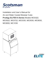
Scotsman MC0330MW Manual
Scotsman
Isterningmaskine
MC0330MW
Læs gratis den danske manual til Scotsman MC0330MW (22 sider) i kategorien Isterningmaskine. Denne vejledning er vurderet som hjælpsom af 7 personer og har en gennemsnitlig bedømmelse på 4.5 stjerner ud af 4 anmeldelser. Har du et spørgsmål om Scotsman MC0330MW, eller vil du spørge andre brugere om produktet?
Side 1/22

Installation and User’s Manual for
Air and Water Cooled Modular Cube
Prodigy ELITE® A Series Models MC0322,
MC0522, MC0722, MC0330, MC0530, MC0630,
MC0830, MC1030

MC0322 through MC1030
Air and Water Cooled User Manual
June 2022
Page 1
Introduction
The design of this modular cuber is the result of years
of experience and testing. Standard features include
front accessible indicator lights and on-o switches
that provide the user with fast access to critical
information and easy operational control. In addition,
the Scotsman ICELINQ® app allows users to connect
to the machine via Bluetooth® to monitor, control, and
maintain the ice machine.
Keep this manual for future reference.
This installation and user manual is divided into
three main sections: Installation, which provides
the trade person with the information needed to set
up and install this product; Use and Operation,
which provides the user with the information to use
the product; and Maintenance, which provides the
user with the information needed keep it operating
eciently.
Note any Caution or Warning symbols when they
appear on the product or in this manual. They indicate
potential hazards.
Contents
Installation: Product Specications . . . . . . . . . . . . . . . . . . . . . . . . . . . . Page 2
Model Number Description . . . . . . . . . . . . . . . . . . . . . . . . . . . . . . . . . . . . . . Page 3
Product Description & Electrical Requirements
. . . . . . . . . . . . . . . . . . . . . . . . . . . . Page 4
MC0322 and MC0522 Cabinet Layout
. . . . . . . . . . . . . . . . . . . . . . . . . . . . . . . . Page 5
MC0722 Cabinet Layout
. . . . . . . . . . . . . . . . . . . . . . . . . . . . . . . . . . . . . . . . Page 6
MC0330, MC0530, MC0630 Cabinet Layout
. . . . . . . . . . . . . . . . . . . . . . . . . . . . . Page 7
MC0830 and MC1030 Cabinet Layout
. . . . . . . . . . . . . . . . . . . . . . . . . . . . . . . . Page 8
Water
. . . . . . . . . . . . . . . . . . . . . . . . . . . . . . . . . . . . . . . . . . . . . . . . . Page 9
Panel Removal
. . . . . . . . . . . . . . . . . . . . . . . . . . . . . . . . . . . . . . . . . . . . Page 10
Plumbing Requirements
. . . . . . . . . . . . . . . . . . . . . . . . . . . . . . . . . . . . . . . . Page 11
Electrical
. . . . . . . . . . . . . . . . . . . . . . . . . . . . . . . . . . . . . . . . . . . . . . . . Page 12
Final Check List
. . . . . . . . . . . . . . . . . . . . . . . . . . . . . . . . . . . . . . . . . . . . Page 13
Initial Start Up
. . . . . . . . . . . . . . . . . . . . . . . . . . . . . . . . . . . . . . . . . . . . . Page 14
Adjustments
. . . . . . . . . . . . . . . . . . . . . . . . . . . . . . . . . . . . . . . . . . . . . . Page 15
Use and Operation . . . . . . . . . . . . . . . . . . . . . . . . . . . . . . . . . . . . . . Page 16
Control Switches. . . . . . . . . . . . . . . . . . . . . . . . . . . . . . . . . . . . . . . . . . . . Page 17
Cleaning, Sanitation and Maintenance . . . . . . . . . . . . . . . . . . . . . . . . . . . Page 18
What to do before calling for service . . . . . . . . . . . . . . . . . . . . . . . . . . . . . . . . . Page 20

MC0322 through MC1030
Air and Water Cooled User Manual
June 2022
Page 3
Model Number Description
Example:
• MC0322SA-1A
• MC= modular cuber
• 03= nominal ice capacity in 100s of pounds
• 22= nominal width of cabinet
• S= Cube size. S=small or half dice cube.
M=medium or full dice cube
• A=Condenser type. A=air cooled. W=water cooled
• -1=115 60 Hz, -32=208-230 60 Hz, -3= 208-230 3
phase 60 Hz
• A=Series revision code.
Note: Listed model numbers typically include only the
rst ve characters of the model number.
Options:
There are several eld-installed options that can be
installed at initial start up or later. They include:
• KVS, Vari-Smart Adjustable ice level system.
• KBILC, Basic Ice Level Control
• KSB, SmartBoard Advanced feature board.
• Side Air Flow Kits:
• PPSA223 (MC0322, MC0522)
• KPPSA22, (MC0722)
• KPPSA323 (MC0330, MC0530, MC0630)
• KPPSA329 (MC0830, MC1030)
• Some installations require bin or dispenser
adapters, see following tables for specic
applications.
Standard Bin Applications - Adapter information.
Model B222
B322
B530P,
B330P,
B530S,
B842S B948S
MC0322,
MC0522,
MC0722
Direct t KBT27 Not
available
Not
available
MC0530,
MC0630,
MC0830,
MC1030
Does not
t
Direct t KBT28 KBT22
Hotel Dispensers
The HD22 and HD30 are compatible with this ice
machine, no adapters are needed. Some typical
combinations include:
• HD22 – use with MC0322 or MC0522
• HD30 – use with MC0330 or MC0530
Ice and Beverage Dispensers – Adapter
information
Model ID150 ID200 or ID250
MC0322,
MC0522,
MC0722
KBT42 KBT43
MC0530,
MC0630,
MC0830,
MC1030
Does not t KBT44
Other Bins & Applications:
Note the drop zone and ice level control sensor
locations in the illustrations on the next pages. A bin
or dispenser top must accommodate their locations.
See sales literature for additional applications and
specialized kits.
Scotsman Ice Systems are designed and
manufactured with the highest regard for safety and
performance.
Scotsman assumes no liability of responsibility of
any kind for products manufactured by Scotsman
that have been altered in any way, including the use
of any part and/or other components not specically
approved by Scotsman.
Scotsman reserves the right to make design changes
and/or improvements at any time. Specications and
design are subject to change without notice.

MC0322 through MC1030
Air and Water Cooled User Manual
June 2022
Page 5
MC0322 and MC0522 Cabinet Layout
57.4
22.58
55.9
22.00
58.2
22.93
LOUVER AND
REMOVABLE FILTER
AC UNITS ONLY
4.2
1.66
7.7
3.04
27.4
10.81
39.1
15.41
3/4" FPT
DRAIN
3/8" FPT
WATER
INLET
.88" DIA
ELECTRICAL
ACCESS
4.3
1.69
3.6
1.44
8.3
3.27
5.1
2.03
38.8
15.29
19
7.48
7.7
3.04
27.4
10.81
37
14.56
3/4" FPT
DRAIN
3/8" FPT
WATER
INLET
.88" DIA
ELECTRICAL
ACCESS
1/2" FPT
CONDENSER
DRAIN
3/8" FPT
CONDENSER
WATER INLET
24.00
REF.
22.00
REF.
2.00
5.1
2.00
5.1
19.05
48.4
3.25
8.3
10.25
26
7.00
17.8
ICE DROP OPENING
ULTRASONIC
BIN LEVEL
SENSOR
(OPTIONAL)
61
24.00
AIR COOLED
BACK VIEW
LEFT SIDE VIEW
FRONT VIEW
WATER COOLED
BACK VIEW
PLAN VIEW

MC0322 through MC1030
Air and Water Cooled User Manual
June 2022
Page 6
MC0722 Cabinet Layout
57.4
22.58
55.9
22.00
73.5
28.93
LOUVER AND
REMOVABLE FILTERS
AC UNITS ONLY
4.3
1.71
42.8
16.85
63.1
24.83
7.8
3.08
6.8
2.68
3/4" FPT
DRAIN
3/8" FPT
WATER
INLET
.88" DIA
ELECTRICAL
ACCESS
24.00
REF.
22.00
REF.
2.00
5.1
2.00
5.1
19.05
48.4
3.25
8.3
10.25
26
7.00
17.8
ICE DROP OPENING
ULTRASONIC
BIN LEVEL
SENSOR
(OPTIONAL)
61
24.00
AIR COOLED
BACK VIEW
LEFT SIDE VIEW
FRONT VIEW
PLAN VIEW

MC0322 through MC1030
Air and Water Cooled User Manual
June 2022
Page 7
MC0330, MC0530, MC0630 Cabinet Layout
30.00
76.2
22.93
58.3
77.6
30.56
LOUVER AND
REMOVABLE FILTER
AC UNITS ONLY
24.00
61
3.06
7.8
10.81
27.5
14.59
37
1.48
3.7
1.73
4.4
1.70
4.3
3/4" FPT
DRAIN
3/8" FPT
WATER
INLET
.88" DIA
ELECTRICAL
ACCESS
1.48
3.8
2.62
6.7
1.57
4
10.25
26
8.62
21.9
14.56
37
10.82
27.5
7.8
3.07
38.9
15.32
3/4" FPT
DRAIN
3/8" FPT
WATER
INLET
.88" DIA
ELECTRICAL
ACCESS
1/2" FPT
CONDENSER
DRAIN
3/8" FPT
CONDENSER
WATER INLET
1.48
3.8
2.63
6.7
1.57
4
15.14
38.5
17.64
44.8
19.04
48.3
3.07
7.8
14.56
37
8.38
21.3
10.82
6.5
2.57
19
7.47
3/4" FPT
DRAIN
3/8" FPT
WATER
INLET
.88" DIA
ELECTRICAL
ACCESS (2)
REMOTE CONDENSER
DISCHARGE LINE
1/2
REMOTE CONDENSER
LIQUID LINE
3/8
24.00
REF.
30.00
REF.
2.00
5.1
2.00
5.1
19.05
48.4
3.25
8.3
10.25
26
7.00
17.8
ICE DROP OPENING
ULTRASONIC
BIN LEVEL
SENSOR
(OPTIONAL)
AIR COOLED
BACK VIEW
LEFT SIDE VIEW
FRONT VIEW
WATER COOLED
BACK VIEW
REMOTE COOLED
BACK VIEW
PLAN VIEW

MC0322 through MC1030
Air and Water Cooled User Manual
June 2022
Page 8
MC0830 and MC1030 Cabinet Layout
24.00
REF.
30.00
REF.
2.00
5.1
2.00
5.1
19.05
48.4
3.25
8.3
10.25
26
7.00
17.8
ICE DROP OPENING
ULTRASONIC
BIN LEVEL
SENSOR
(OPTIONAL)
30.00
76.2
77.67
30.58
73.5
28.93
LOUVERS AND
REMOVABLE FILTERS
AC UNITS ONLY
24.00
61
3.7
1.73
4.4
1.70
4.3
3.06
7.8
13.44
34.1
20.56
52.2
3/8" FPT
WATER
INLET
3/4" FPT
DRAIN
.88" DIA
ELECTRICAL
ACCESS
4.87
12.4
1.75
4.4
5.69
14.4
13.47
34.2
3.4
1.35
7.6
3.01
43.5
17.14
52.2
20.56
3.4
1.34
10.8
4.24
3/8" FPT
WATER
INLET
3/4" FPT
DRAIN
.88" DIA
ELECTRICAL
ACCESS
3/8" FPT
CONDENSER
WATER INLET
1/2" FPT
CONDENSER
DRAIN
24.60
62.5
16.54
42
14.63
37.1
2.34
5.9
3.07
7.8
13.47
34.2
1.48
3.8
1.75
4.4
2.2
.88
54.4
21.44
3/8" FPT
WATER
INLET
3/4" FPT
DRAIN
REMOTE CONDENSER
LIQUID LINE
3/8
REMOTE CONDENSER
DISCHARGE LINE
1/2
.88" DIA
ELECTRICAL
ACCESS (2)
AIR COOLED
BACK VIEW
LEFT SIDE VIEW
FRONT VIEW
WATER COOLED
BACK VIEW
REMOTE COOLED
BACK VIEW
PLAN VIEW

MC0322 through MC1030
Air and Water Cooled User Manual
June 2022
Page 9
Water
The quality of the water supplied to the ice machine
will have an impact on the time between cleanings
and ultimately on the life of the product. Water can
contain impurities either in suspension or in solution.
Suspended solids can be ltered out. In solution
or dissolved solids cannot be ltered, they must be
diluted or treated. Water lters are recommended
to remove suspended solids. Some lters have
treatment in them for suspended solids. Check with a
water treatment service for a recommendation.
RO Water
This machine can be supplied with Reverse Osmosis
water, but the water conductivity must be no less than
10 microSiemens/cm.
Potential for Airborne Contamination
Installing an ice machine near a source of yeast
or similar material can result in the need for more
frequent sanitation cleanings due to the tendency of
these materials to contaminate the machine.
Most water lters remove chlorine from the water
supply to the machine which contributes to this
situation. Testing has shown that using a lter that
does not remove chlorine, such as the Scotsman
AquaPatrol™, will greatly improve this situation, while
the ice making process itself will remove the chlorine
from the ice, resulting in no taste or odor impact.
Additionally, devices intended to enhance ice machine
sanitation, such as the Scotsman AquaBullet®, can
be placed in the machine to keep it cleaner between
manual cleanings
Water purge
Cube ice machines use more water than what ends
up in the bin as ice. While most water is used during
ice making, a portion is designed to be drained out
every cycle to reduce the amount of hard water scale
in the machine. That’s known as water purge, and
an eective purge can increase the time between
needed water system cleaning. In addition, this
product has the capability to automatically vary the
amount of water purged based on the purity of the
water supplied to it. The water purge rate can also be
set manually. Adjustments of purge due to local water
conditions are not covered by warranty.

MC0322 through MC1030
Air and Water Cooled User Manual
June 2022
Page 10
Panel Removal
1. Locate and disengage the two quarter turn
captured screws at the bottom of the front panel.
2. Pull the front panel out at the bottom.
3. Lift the front panel up and o the machine.
4. Remove two screws at the front of the top panel.
Lift up the front of the top panel, push the top
panel back an inch, then lift to remove.
5. Locate and loosen the screws holding each side
panel to the base. Left side panel also has a
screw holding it to the control box.
6. Pull the side panel forward to release it from the
back panel.
Model and Serial Numbers
This manual covers several models. The model
number on the product is located in two places, on the
back dataplate and on the model and serial number
tag, located behind the front panel. See the illustration
for the dataplate and serial tag locations.
Write the model and serial number of this product
here:
________________________________________
Write the day, month and year of initial start up here:
________________________________________
Switch Door
All models ship with the indicator lights visible at
the lower left front. The On and O buttons and the
Bluetooth® button are covered by a door to the right
of those lights. The on and o buttons and indicator
lights duplicate what is on the controller.
Uncrate and Set Up
Begin with unpacking the ice storage bin. Remove the
carton, and using part of the carton as a cushion, tip
the bin on its back to remove the skid and attach the
legs or casters.
Return the bin to an upright position. Check the bin
top gasket for gaps and tears, ll any in with food
grade sealant prior to placing the ice machine on the
bin.
Install the bin top adapter or ice dispenser adapter, if
one is required for the application.
If the ice machine has not been unpacked, do so now.
Remove the carton from the skid. Lift the ice machine
o the skid directly onto the bin.
Note: The machine is heavy! Use a mechanical hoist
if necessary.
Secure the ice machine to the bin with the hardware
provided (two metal straps and 4 bolts).
Place the bin and ice machine in the selected location
and level it by adjusting the bin leg levelers.
Remove the white plastic covering the panels.
Dataplate
Location
5. Remove
Screws
2
6
4
6
3
1. Disengage
1/4 Turn
Screws
Dataplate Location and Panel Removal

MC0322 through MC1030
Air and Water Cooled User Manual
June 2022
Page 11
Plumbing Requirements
All models require connection to cold, potable water.
A hand actuated valve within sight of the machine
is required. Air cooled models have a single 3/8”
FPT inlet water connection; a 3/8” FPT to 3/8” male
are adapter is available from the local Scotsman
distributor or from a hardware store.
Water cooled models have a 1/2" FPT drain tting
plus an additional 3/8” FPT condenser inlet water
connection.
Water Filters
If connecting to water ltration, lter only the water
to the reservoir, not to the condenser. Install a new
cartridge if the lters were used with a prior machine.
All models require drain tubing to be attached to
them. Air cooled models have a single 3/4” FPT drain
tting in the back of the cabinet. Water cooled models
have the same tting plus an additional 1/2” FPT drain
tting in the back of the cabinet.
Install new tubing when replacing a prior ice machine,
as the tubing will have been sized for the old model
and might not be correct for this one.
1. Connect water supply to water inlet ttings. 3/8" OD
tubing is recommended.
Note: This NSF listed model has a 1" anti-back ow
air break between the water inlet tube end and the
highest possible reservoir water level, no back ow
device is required for the potable water inlet.
2. Connect drain tubing to drain ttings.
3. Route the drain tubing to building drain. Follow
local codes for air gap to drain receptacle.
Drain Tubing:
Use rigid drain tubes and route them separately – do
not Tee into the bin’s drain and, if water cooled,do not
Tee the condenser drain into the reservoir or bin drain.
Vent the reservoir drain. A vertical vent at the back of
the drain, extended about 8 - 10” will allow the gravity
drain to empty and also keep any surges during
draining from discharging water out the vent.
Insulate drain tubing if in a humid environment.
Horizontal runs of drain tubing need a 1/4” fall per foot
of run for proper draining.
Follow all applicable codes.
Water Fitting
Plumbing Connections
Water Cooled Shown, Air Cooled Similar
Inlet Water
Connection
Water
Supply
Water Cooled
Supply
Water
Cooled
Drain
Floor Drain
Potable
Water
Connection
Drain Vent
Reservoir
Drain
Connection
Bin Drain
Connection

MC0322 through MC1030
Air and Water Cooled User Manual
June 2022
Page 13
Final Check List
After connections,
1. Wash out the bin. If desired, the interior of the bin
could be sanitized.
2. Locate the ice scoop (if supplied) and have it
available for use when needed.
Final Check List:
1. Is the unit located indoors in a controlled
environment?
2. Is the unit located where it can receive adequate
cooling air?
3. Has the correct electrical power been supplied to
the machine?
4. Have all the water supply connections been
made?
5. Have all the drain connections been made?
6. Has the unit been leveled?
7. Have all unpacking materials and tape been
removed??
8. Is the water pressure adequate?
9. Have the drain connections been checked for
leaks?
10. Has the bin interior been wiped clean or sanitized?
11. Have any water lter cartridges been replaced?
12. Have all required kits and adapters been properly
installed?
Lower Light and Switch Panel
This user accessible panel provides important
operational information and duplicates the lights and
switches on the controller. It also allows access to the
On and O buttons that operate the ice machine.
Sometimes access to the switches should be limited
to prevent unauthorized operation. For that purpose a
xed panel is shipped in the hardware package. The
xed panel cannot be opened.
To install the xed panel:
1. Remove the front panel.
2. From the back side of the panel, slide the door
to left while spreading the clips to remove the
original door from the bezel.
3. Slide the xed panel into bezel until it snaps into
place.
4. Reinstall front panel.
Open door to access On
and O switch buttons.

MC0322 through MC1030
Air and Water Cooled User Manual
June 2022
Page 14
Initial Start Up
1. Remove front panel and evaporator cover. Check
machine for any packing or wires rubbing moving
parts.
2. Switch on the electrical power to the machine.
Observe that some of the control’s indicator lights
glow and its display shows O.
3. Open the water supply valve.
4. Locate lower light and switch panel. Push and
release the ON button on that panel. The code
display will begin to blink F.
The purge valve opens, the water pump starts and
the inlet water valve opens to add water to the
reservoir. In a few seconds the purge valve closes
and the water pump stops. Water will ow into the
machine until the reservoir is full. The hot gas valve
and harvest assist device will activate, then the
compressor and water pump will start. If it’s an air
cooled model, the fan motor(s) will begin to turn a few
moments after the compressor starts. The display
will show a continuous F. Five seconds later the hot
gas valve will close and the harvest assist device
will return to its standby position. Warm air will be
discharged from air cooled models.
5. Observe the Ready for Harvest indicator light. It
may blink early in the cycle, that is normal. The
control will ignore that signal for the rst 6 minutes
of freeze.
6. During the Freeze cycle move the curtain and
observe that the SW1 or SW2 light on the control
board blinks On when the curtain moves away
from the evaporator and O when returned to its
normal position.
Note: Moving the curtain during the Freeze cycle has
no aect on control function, but will cause water to
ow into the cube chute/bin.
7. When enough ice has frozen, the Ready for
Harvest indicator light will be on steady. After it’s
been on steady for a few seconds Harvest will
begin.
8. The display shows an H.
The hot gas valve opens, the air cooled fan motor(s)
shut o and the harvest assist mechanism is
activated. The purge valve opens to drain some water,
when it does the inlet water valve opens to rell the
reservoir. After a few seconds the purge valve closes
but the inlet water valve continues to ll the reservoir.
Harvest continues until the ice is released as a unit
and forces the curtain to open. When the curtain
opens it signals the controller which returns the unit to
a freeze cycle.
9. Check the ice harvested for proper bridge
thickness. The ice bridge is factory set at 1/8 inch.
If needed, adjust bridge thickness. Do NOT make
it too thin.
10. Return the front panel and evaporator cover to
their normal positions and secure to the machine.
11. Instruct the user in the operation of the machine
and its maintenance requirements.
12. Fill out and mail the warranty registration form or
register it on line at Scotsman-ice.com.
Typical Ice Making Cycle Times (minutes).
Listed times are for clean machines in proper
installations. Cycle length at startup will be longer until
the system stabilizes.
Model 70
o
F air / 50
o
F.
water
90
o
F. air / 70
o
F.
water
MC0322A 10-12 14-16
MC0322W 9-11 10-12
MC0522A 11-13 16-18
MC0522W 13-15 13-15
MC0330A 9-11 12-14
MC0330W 8-10 9-11
MC0530A 12-14 16-18
MC0530W 10-12 11-13
MC0630A 9-11 1 1-13
MC0630W 7-9 10-12
MC0722A 13-15 19-22
MC0830A 10-12 13-15
MC0830W 11-13 12-14
MC1030A 9-11 11-13
MC1030W 9-11 10-12

MC0322 through MC1030
Air and Water Cooled User Manual
June 2022
Page 15
Adjustments
Bridge Thickness - For the Service Tech Only
1. Push and hold O till the machine stops.
2. Remove evaporator cover.
3. Remove curtain.
4. Use a hex wrench and rotate the bridge thickness
adjustment screw in 1/8” turn increments CW to
increase bridge thickness.
5. Rotate CCW to decrease bridge thickness.
Caution: Do not make the bridge too thin or the
machine will not harvest properly. Bridge thickness
adjustments are not covered by warranty.
6. Return curtain and evaporator cover to their
normal positions.
7. Push and release the On button. Check next
harvest of ice. Repeat steps 1-6 if needed.
Water Purge Setting
The water purge is factory set to the automatic
position, suitable for most water conditions. The
setting can be changed to one of 5 manual settings or
left on automatic.
Purge setting 1 - Minimum 2 - Moderate 3 - Standard 4 - Heavy 5 - Maximum A - Automatic
Water Type RO water or
equivalent
Low TDS
non - RO
water
Use for typical
water
High TDS
water
Very High TDS
water
Any with
conductivity not
less than 10
microSiemens/
cm
To set:
1. Switch the machine OFF by holding the O button
in until a number or the letter A shows on the
display.
2. Press and release the On button repeatedly until
the number on the display corresponds to the
desired setting.
3. Press and release the O switch again to return to
the normal control state.
Bridge Thickness Adjustment Mechanism
Note: Water cooled models- the refrigeration system
discharge pressure is factory set at 245 PSIG,
which should yield a freeze cycle discharge water
temperature of about 105-110 degrees F. Adjust if
necessary.
Note: Indentations may be deeper on MC0322 and MC0330
Ice Bridge Thickness Measurement
Adjustment
Screw
1/8-3/16”
bridge
Too Big
Just Right
Too Small

MC0322 through MC1030
Air and Water Cooled User Manual
June 2022
Page 16
Use and Operation
Once started, the ice machine will automatically make
ice until the bin or dispenser is full of ice. When ice
level drops, the ice machine will resume making ice.
Caution: Do not place anything on top of the ice
machine, including the ice scoop. Debris and moisture
from objects on top of the machine can work their way
into the cabinet and cause serious damage. Damage
caused by foreign material is not covered by warranty.
There are ve indicator lights at the front of the
machine that provide information on the condition of
the machine.
Indicator Lights:
• Power
• Status
• Water
• Clean (De-scale & Sanitize)
• Bin Full
Indicator Lights & Their Meanings
Power Status Water De-Scale & Sanitize Bin Full
Steady
Green
Normal Normal – bin full or
making ice
- - Bin is full
Blinking
Green
Self Test
Failure
Switching on or o - -
Blinking
Red
- Diagnostic shutdown or, if
making ice, temperature
sensor failure
Lack of water -
Yellow - - - Time to de-scale and
sanitize
Blinking
Yellow
- - - Preservation Mode is
active or clean cycle is
in progress
Light o No power Switched o Normal Normal Bin is not
full
If the Water light is on, the machine has sensed a
lack of water. Check the water supply to the machine.
The water could have been shut o or the water lter
cartridges might need to be changed.
If the Clean light is solid yellow, the machine has
determined that it needs to be cleaned. Contact an
authorized Scotsman service agent and have the
machine cleaned, de-scaled and sanitized.
During normal operation, if the Clean light begins to
blink yellow, the machine in Preservation mode, which
initiates a timed freeze in response to short freeze
errors. Contact an authorized Scotsman service agent
to service the machine immediately. It is likely that
the machine needs to be cleaned (de-scaled and
sanitized), but may need additional service.
Note: A Component Indicator Light switches ON to
indicate that the component is operating.
Note: There are two Curtain Switch lights, SW1 and
SW2. These single plate models have one curtain
switch light on all the time, as a curtain switch light is
ON when a curtain is either open or not present.

MC0322 through MC1030
Air and Water Cooled User Manual
June 2022
Page 17
Control Switches
The On and O switch buttons are front accessible.
To switch the machine OFF, push and release the O
button. The machine will shut o at the end of the next
cycle. To shut the machine o immediately, push and
hold the O button for 3 seconds.
To switch the machine ON, push and release the
On button. The machine will go through a start up
process and then resume ice making.
Control Options
There are two optional, eld installed controls that can
be added to this machine.
• Vari-Smart™ adjustable ice level control
• Smart-Board™ advanced control board and data
logger
Adjustable ice level control
When this option is present there is an adjustment
post and an additional indicator light to the right
of the controller switches. The ultrasonic ice level
control allows the user to control the point that the
ice machine will stop making ice before the bin or
dispenser is full. Reasons for this include:
• Seasonal changes in ice used
• Planning to sanitize the bin
• Faster turnover for fresher ice
• Certain dispenser applications where maximum
ice level is not desired
Note: Ice will build up in the bin or dispenser at an
angle, the distance set will be from the sensor to the
top of the ice. The sensor position is shown in the
cabinet layout diagrams.
The actual distance between the highest point of the
ice may be closer or further away than the distance
set, depending upon the angle of the ice.
Use of control
There are several positions the ice level can be set to,
including O or Max (knob and label indicators lined
up), where it lls the bin until the standard bin control
shuts the machine o. See the kit’s instructions for
complete details.
Rotate the adjustment post to the desired ice level.
The machine will ll up to that level and when it shuts
o the Bin Full indicator light will be On.
Ice
The cuber drops ice in large sections. That ice will
break up into random parts as it falls into the bin, but
some large sections may remain on top of the ice
in the bin. In a dispenser, this ice will break up into
mostly individual cubes as the dispense mechanism
moves the ice. The ice in the bin will normally slope
down from the right to the left.
Heat
When making ice, air-cooled models will discharge
hot air out the back of the cabinet.
Noise
The ice machine will make noise when it is in ice
making mode. The compressor, fan motor(s) if air
cooled, and water pump all produce some sound. It
is also normal to hear some cracking just before the
harvest cycle begins. In addition, during the harvest
cycle the harvest mechanism may click twice as it
pushes the ice out and returns to its normal position.
The ice harvests as a unit or slab, which makes some
noise when it impacts the bin or dispenser. These
noises are all normal for this machine.
POWER STATUS WATER CLEAN
ICE PRODUCTION
MANUAL
HARVEST
INITIATE
CLEAN
OPTIONAL KVS PLACED HERE
(Vari-Smart
TM
Adjustable Ice Level Control)
The following codes will be displayed when
unit is operating as expected:
F
- Freeze
H
- Harvest
B
- Bin Full
O
- Standby/Off
Additional operational and error codes can
be found on the inside of the front panel.
Scan QR code to download the Scotsman ICELINQ™ App:
Connect to this machine via Bluetooth to access additional machine operations,
view error information, adjust settings, and initiate self-guided cleaning.
ON OFF
02-5166-01
OPTIONAL KSBU, KPAS, KSBU-N PLACED HERE
(Smart-Board™ Advanced Control Panel)
Component Operation Indicator Lights

MC0322 through MC1030
Air and Water Cooled User Manual
June 2022
Page 19
Cleaning, Sanitation and Maintenance Continued
Sanitize:
13. Push and release the Clean button. The yellow
Clean light will blink and the display will show C.
The machine will go through a harvest cycle, drain
the reservoir and begin to rell it.
14. Observe code display, when it blinks the
characters “A d 1” immediately go to the next
step.
15. Pour the previously prepared sanitizing solution
into the reservoir until it is full. The unit will circulate
the sanitizer, then drain and ush it. This will take
35 minutes, then the machine will stop and the
display will show O.
16. Remove all ice from storage bin or dispenser and
sanitize bin or dispenser with remaining sanitizing
solution while machine completes sanitizing cycle.
Pour excess sanitizer down drain.
Finish Cleaning Process:
17. Reinstall evaporator cover and front panel (with
air lter(s) if applicable) in their original positions.
18. Push and release the “ON” button to resume ice
making.
Want more guidance?
Scan QR Code to download the Scotsman ICELINQ®
App to connect to this machine via Bluetooth® and
access the self-guided cleaning process.
Additional maintenance:
Air lter (air-cooled models)
Clean air lters when they become visibly dirty. They
will need cleaning more often than the other items.
1. Pull air lter(s) from the front panel.
2. Wash the dust and grease o the lter.
3. Return it to its original position.
Do not operate the machine without the lter in place
except during cleaning.
Condenser (air-cooled models)
If the machine has been operated without a lter the
air cooled condenser ns will need to be cleaned.
They are located under the fan blades. The services
of a refrigeration technician will be required to clean
the condenser.
Exterior panels
The front, top and side panels are durable stainless
steel. Fingerprints, dust and grease will require
cleaning with a good quality stainless steel cleaner.
Note: If using a sanitizer or a cleaner that contains
chlorine on the panels, after use be sure to wash the
panels with clean water to remove chlorine residue.
Water lters
If the machine has been connected to water lters,
check the cartridges for the date they were replaced
or for the pressure on the gauge. Change cartridges
if they’ve been installed more than 6 months or if the
pressure drops too much when the ice machine lls
with water.

MC0322 through MC1030
Air and Water Cooled User Manual
June 2022
Page 20
What to do before calling for service
Reasons the machine might shut itself o:
• Lack of water.
• Freeze cycle takes too long.
• Harvest cycle takes too long.
• High discharge temperature.
• Controller self test failure.
Check the following:
1. Has the water supply to the ice machine or
building been shut o? If yes, the ice machine will
automatically restart within 25 minutes after water
begins to ow to it.
2. Has power been shut o to the ice machine? If
yes, the ice machine will automatically restart
when power is restored.
3. Has someone shut the water o to a water
cooled unit? If yes, after the water supply has
been restored the ice machine may need to be
manually reset.
4. Is the curtain open because some ice is stuck
under it? If so, remove the ice and the machine
should start in a few minutes.
To Manually Reset the machine.
• Open the switch door
• Push and release the O button.
• Push and release the On button.
To Shut the Machine O:
1. Push and hold the O button for 3 seconds or until
the machine stops.
2.
Note: Curtain can be removed & replaced anytime the
machine is in a standby mode or when it is in a freeze
cycle. However, removal of the curtain during freeze
will result in water owing into the bin. Removal of the
curtain during harvest terminates harvest at that point
and, if left o, will result in the machine shutting o.
• View machine status
• Control machine operation
• Adjust machine settings
• View active errors with troubleshooting tips
• Initiate self-guided cleaning
• Access service resources and warranty info
Scan QR Code to download the
Scotsman ICELINQ® App
Curtain
Clear Ice
From Here
Clear Ice From Beneath Curtain
Scotsman ICELINQ® Mobile App
All Prodigy ELITE® models are Bluetooth® enabled
and are compatible with the Scotsman ICELINQ®
app, available on both the Apple App Store and
Google Play Store.
The ICELINQ mobile app uses Bluetooth connectivity
to allow users to easily monitor, control, and maintain
their machine:
Open Door to Reset or Switch O

17-3737-01
SCOTSMAN ICE SYSTEMS
101 Corporate Woods Parkway
Vernon Hills, IL 60061
www.scotsman-ice.com
800-726-8762
Produkt Specifikationer
Mærke: | Scotsman |
Kategori: | Isterningmaskine |
Model: | MC0330MW |
Har du brug for hjælp?
Hvis du har brug for hjælp til Scotsman MC0330MW stil et spørgsmål nedenfor, og andre brugere vil svare dig
Isterningmaskine Scotsman Manualer
14 Juni 2025
14 Juni 2025
14 Juni 2025
22 Maj 2024
Isterningmaskine Manualer
- NewAir
- GE
- Sonnenkönig
- Bartscher
- Wëasy
- Hoshizaki
- Trebs
- U-Line
- Domo
- Ice-O-Matic
- Livoo
- H.Koenig
- XO
- Witt
- Klarstein
Nyeste Isterningmaskine Manualer
20 Juni 2025
20 Juni 2025
20 Juni 2025
20 Juni 2025
20 Juni 2025
20 Juni 2025
20 Juni 2025
20 Juni 2025
20 Juni 2025
20 Juni 2025