Smart365 SM-04-02050 Manual
Læs gratis den danske manual til Smart365 SM-04-02050 (40 sider) i kategorien Sav. Denne vejledning er vurderet som hjælpsom af 31 personer og har en gennemsnitlig bedømmelse på 4.4 stjerner ud af 16 anmeldelser.
Har du et spørgsmål om Smart365 SM-04-02050, eller vil du spørge andre brugere om produktet?
Produkt Specifikationer
| Mærke: | Smart365 |
| Kategori: | Sav |
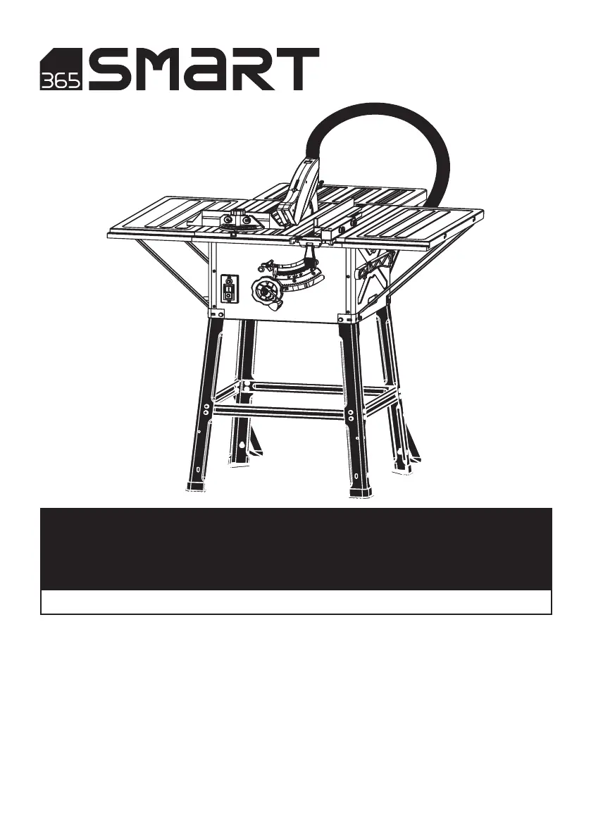
| Model: | SM-04-02050 |
Har du brug for hjælp?
Hvis du har brug for hjælp til Smart365 SM-04-02050 stil et spørgsmål nedenfor, og andre brugere vil svare dig
Sav Smart365 Manualer

Sav Manualer
- Bosch
- Extralink
- Martha Stewart
- Batavia
- Yato
- McCulloch
- Graphite
- Dual Saw
- Gardol
- Mastercraft
- Maktec
- Flex
- Efco
- Echo
- Parkside
Nyeste Sav Manualer


