Technical characterisƟ cs
Protec on class: Class I
Temperature range: 0 ... 40°C
Ambient temperature limits: -20/+50°C
Accuracy: ± 2 K a 40°C / ± 4 K a 0°C
Maximum load: (*resis ve load **induc ve load)
- Connec on 1-3: 16* (4**)A 250 VAC, 10* (4**)A 400 VAC
- Connec on 1-2: 8* (4**)A 250 VAC, 4* (2**)A 400 VAC
Ambient thermostat THE 16/4
Ambient thermostat THE 16/4A
The wide range of S&P Offi cial Services network guaran-
tees competent technical assistance anywhere. If any ano-
malies are observed in this device, please contact any of
Technical Services on the list to deal with your problem.
Any manuipula on done over this device by others out of
S&P Offi cial Services will lead to cancel guarantee.
EU regula ons and our commitment to future genera ons
oblige us to recycle used materials; please remember to
dispose of all unwanted packaging materials at the appro-
priate recycling points, and to drop off obsolete equip-
ment at the nearest waste management point.
Soler & Palau reserves the right to modify this manual without prior
THE 16/4 & THE 16/4A THERMOSTAT
We recommend to verify if model and features correspond
to device ordered. This product must be stored in its orig-
inal packaging, in a dry place and protected from outdoor.
Storage temperature between -10ºC and +40ºC.
The thermostat controls a load un l 16A if this is resis ve
(heater) and un l 4A if the load is induc ve (motor).
Ambient thermostat THE 16/4
Adjustment is made with poten ometer on the product
Ambient thermostat THE 16/4A
Adjustment poten ometer is located inside the device.
To change the setpoint it is required to remove the cover.
InstallaƟ on and maintenance
Thermostat has to be installed in a suitable place where
local temperature is representa ve with air circula on.
Do not install in a corner without air movement, near a
heater or a window, nor in a place exposed to sun light.
Ambient thermostat THE 16/4
To wire it, remove the knob and cover.
Ambient thermostat THE 16/4A
To wire it, remove the cover of the box.
Electrical connec on as indicated in wiring diagram.
Before installing and connecƟ ng this device, be sure that
power supply is disconnected.
The installa on has to be done by a qualifi ed professional
and should be done in accordance with current local re-
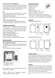
Wire as indicated in following wiring diagram:
Winter: COM-NC, when temperature selected is reached,
hea ng system is stopped.
Summer: COM-NO, when temperature selected is
reached, ven la on system is ac vated.