Sonel CS-1 Manual


Læs gratis den danske manual til Sonel CS-1 (2 sider) i kategorien Ikke kategoriseret. Denne vejledning er vurderet som hjælpsom af 4 personer og har en gennemsnitlig bedømmelse på 4.4 stjerner ud af 2.5 anmeldelser. Har du et spørgsmål om Sonel CS-1, eller vil du spørge andre brugere om produktet?

Side 1/2
SYMULATOR KABLA
CS-1
INSTRUKCJA OBSŁUGI
Wersja 1.01 06.10.2023
1 Opis
Akcesorium służy celom szkoleniowym, prezenta-
cyjnym i pomocniczo do zgrubnego oszacowania
poprawności pomiaru rezystancji. Wyniki otrzyma-
ne przy pomiarach wykonywanych na symulatorze
należy traktować szacunkowo a nie jako wyniki
wzorcujące. Symulator kabla CS-1 przeznaczony
jest do symulowania rezystancji izolacji przewo-
dów energetycznych. W adapterze zastosowano
gniazda bananowe o średnicy 4 mm. Umożliwia to
dokonywanie pomiarów rezystancji większością
mierników do tego przeznaczonych znajdujących
się w ofercie Sonel S.A.. Użytkownik wykorzystu-
jąc symulator kabla, jest w stanie sprawdzić po-
prawność wykonywania pomiarów urządzeniami
serii MIC miernikami rezystancji izolacji. Pozo-
stałymi urządzeniami przeznaczonymi do współ-
pracy z symulatorem m.in. wielofunkcyjne
mierniki parametrów instalacji elektrycznych, które
zostały wyposażone w funkcję pomiaru rezystancji
izolacji. Należy pamiętać, że wyniki prezentowane
na wyświetlaczu mierników są orientacyjne, a war-
tość zawiera się w granicach błędu podstawowego
samego miernika i symulatora kabla. Uzyskiwana
dzięki symulatorowi rezystancja może przez długi
czas przebywpod zewnętrznym napięciem sta-
łym do 1000 V. Obudowa cechuje się wysoką od-
pornością na uszkodzenia mechaniczne. Akceso-
rium pozwala na wykonanie symulacji pomiarów
czterech wielkości rezystancji.
W związku z ciągłym prowadzeniem prac w kie-
runku udoskonalenia wyrobu, podwyższenia jego
parametrów technicznych i użytkowych, możliwe
nieznaczne zmiany konstrukcyjne, nie odzwier-
ciedlone w niniejszym wydaniu instrukcji.
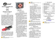
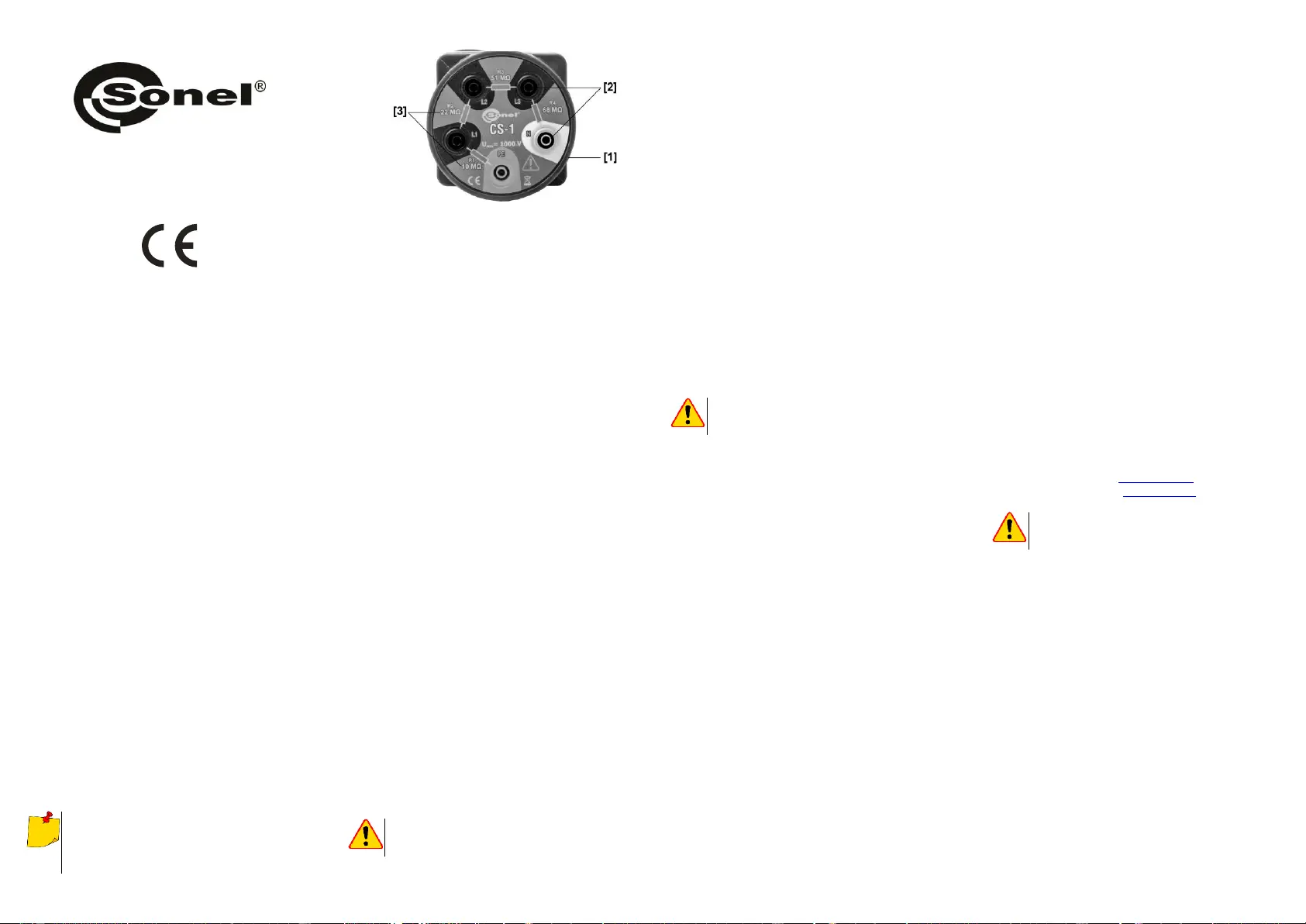
[1] obudowa
[2] gniazda pomiarowe
[3] wielkości rezystancji obwodów pomiarowych
2 Bezpieczeństwo
Aby zapewnić odpowiednią obsługę przyrządu
i poprawność uzyskiwanych wyników należy prze-
strzegać następujących zaleceń:
Przed rozpoczęciem eksploatacji akcesorium
należy dokładnie zapoznać się z niniejszą in-
strukcją i zastosow s do przepisów bez-
pieczeństwa i zaleceń producenta.
Każde inne zastosowanie akcesorium niż po-
dane w tej instrukcji może spowodow jego
uszkodzenie i być źródłem poważnego nie-
bezpieczeństwa dla użytkownika.
Akcesorium powinno b obsługiwane wy-
łącznie przez osoby odpowiednio wykwalifi-
kowane posiadające wymagane uprawnienia
do przeprowadzania pomiarów w instalacjach
elektrycznych. Posługiwanie się symulatorem
przez osoby nieuprawnione może spowodo-
wać jego uszkodzenie i być źródłem poważ-
nego niebezpieczeństwa dla użytkownika.
Akcesorium nie wolno stosować do sieci i
urządzeń w pomieszczeniach o specjalnych
warunkach, np. o atmosferze niebezpiecznej
pod względem wybuchowym i pożarowym.
Nie wolno przekraczać maksymalnego do-
puszczalnego zakresu napięcia wejściowego.
Podczas pracy z symulatorem należy używać
odpowiednich końcówek pomiarowych.
Przed pomiarem należy sprawdzić czy prze-
wody pomiarowe podłączone do odpo-
wiednich gniazd pomiarowych.
Niedopuszczalne jest używanie:
akcesorium, które uległo uszkodzeniu i
jest całkowicie lub częściowo niesprawne,
akcesorium przechowywanego zbyt długo
w złych warunkach (np. zawilgoconego).
UWAGA!
Symulatora nie wolno podłączać do sieci elektroe-
nergetycznej.
3 Użytkowanie
Przed użyciem akcesorium sprawdzić, czy o-
budowa nie jest uszkodzona.
Aby wykonać pomiar jednej z czterech wielko-
ści rezystancji należy przewody podłączone
do gniazd Riso+ i Riso- w mierniku podłączyć
do jednego z obwodów na symulatorze.
Ustawić w mierniku napięcie pomiarowe,
maksymalnie 1000 V.
Rozpocząć pomiar wciskając odpowiedni
przycisk w mierniku.
Po zakończeniu pomiaru odczytać wartość
pomiaru z wyświetlacza.
Wielkość rezystancji izolacji po pomiarze
wskazana na wyświetlaczu, powinna zgadz
się z wartością rezystancji badanego obwodu.
Podczas odczytu wartości z wyświetlacza
urządzenia pomiarowego należy pamiętać o
błędzie pomiarowym określonym w specyfika-
cji technicznej.
4 Czyszczenie i konserwacja
UWAGA!
Należy stosować jedynie metody konserwacji po-
dane przez producenta w niniejszej instrukcji.
Symulator można czyścić miękką, wilgotną
flanelą używając ogólnie dostępnych detergentów.
Nie należy używać żadnych rozpuszczalników, ani
środków czyszczących, które mogłyby porysować
obudowę (proszki, pasty itp.).
5 Magazynowanie
Urządzenie przechowywać w pomieszczeniu
suchym o wilgotności nie przekraczającej wartości
podanej w instrukcji.
6 Rozbiórka i utylizacja
Zużyty sprzęt elektryczny i elektroniczny nale-
ży gromadzić selektywnie, tj. nie umieszczać z
odpadami innego rodzaju.
Zużyty sprzęt elektroniczny należy przekazać
do punktu zbiórki zgodnie z Ustawą o zużytym
sprzęcie elektrycznym i elektronicznym.
Przed przekazaniem sprzętu do punktu zbiórki
nie należy samodzielnie demontować żadnych
części z tego sprzętu.
Należy przestrzegać lokalnych przepisów do-
tyczących wyrzucania opakowań, zużytych baterii
i akumulatorów.
7 Dane techniczne
a) rodzaj izolacji zgodnie z PN-EN 61010-1 ................ podwójna
b) stopień ochrony obudowy wg PN-EN 60529 .................. IP40
c) maksymalne napięcie pomiarowe ........................ 1000 VDC
d) wartość rezystancji na danych obwodach .............................
............................................. 10 MΩ, 22 MΩ, 51 MΩ, 68 MΩ
e) błąd podstawowy odczytywanych wartości ....................± 1%
f) temperaturowy współczynnik rezystancji / stabilność rezy-
stancji w funkcji temperatury: ....... ±200ppm na każdy ± 1°C
g) czasowy współczynnik rezystancji / stabilność rezystancji w
funkcji czasu ............................................................................
................. po upływie 1000 godzin zmiana rezystancji ± 5%
h) wymiary ........................................................ 87 x 87 x 58 mm
i) masa .............................................................................. 142 g
j) temperatura pracy .............................................. 0°C+60°C
k) wilgotność względna ............................................ 20%90%
l) maksymalna wysokość pracy ......................... 2000 m n.p.m.
m) temperatura przechowywania ........................ -30°C+65°C
n) gniazda bananowe ............... pięć gniazd bananowych 4 mm
o) standard jakości .....................................................................
............ opracowanie, projekt i produkcja zgodnie z ISO 9001
8 Producent
Producentem przyrządu prowadzącym serwis
gwarancyjny i pogwarancyjny jest:
SONEL S.A.
ul. Wokulskiego 11
58-100 Świdnica
tel. +48 74 884 10 53 (Biuro Obsługi Klienta)
e-mail: bok@sonel.pl
internet: www.sonel.pl
UWAGA!
Do prowadzenia napraw serwisowych upoważnio-
ny jest jedynie producent.
CS-1
CABLE SIMULATOR
USER MANUAL
Version 1.01 06.10.2023
1 Description
This accessory is designed for training and
presentation purposes and for providing rough es-
timates of resistance measurement accuracy. The
results obtained from the measurements with the
simulator shall be treated as estimated values,
and not as calibration results. CS-1 cable simula-
tor is designed to simulate the insulation re-
sistance of power cables. The adapter is equipped
with banana sockets with a diameter of 4 mm.
This allows user to perform resistance measure-
ments with majority of meters designed for this
purpose and offered by Sonel SA. The user of the
cable simulator is able to check the correctness of
measuring results provided by devices of MIC se-
ries (insulation resistance meters). Other devices
compatible with CS-1 include multifunctional elec-
trical installation meters, with the function of insu-
lation resistance measurement. Please note that
the results presented in the display of the meters
are approximate, and that presented value is with-
in the basic error range of the meter itself and the
cable simulator. The resistance value provided by
the simulator may for a long time remain under
constant external voltage, up to 1000 V. The hous-
ing is highly resistant to mechanical damage. The
device allows user to perform a simulation of
measurements for four resistance values.
Due to continuous product improvement and in-
creasing its technical parameters and perfor-
mance, there may be slight design changes, not
reflected in this edition of the manual.
[1] housing
[2] measuring terminals
[3] resistance values of measuring circuits
2 Safety
In order to provide conditions for correct oper-
ation and the correctness of the obtained results,
the following recommendations must be observed:
Before you proceed to operate the device, ac-
quaint yourself thoroughly with this manual
and observe the safety regulations and speci-
fications provided by the producer.
Any application that differs from those speci-
fied in the present manual may result in a
damage to the device and constitute a source
of danger for the user.
The accessory should be operated only by
suitably qualified persons having the neces-
sary permissions to carry out measurements
on electrical systems. Operating the simulator
by unauthorised personnel may result in dam-
age to the device and constitute a source of
danger for the user.
The accessory must not be used for networks
and devices in areas with special conditions,
e.g. fire-risk and explosive-risk areas.
Do not exceed the maximum allowable input
voltage range.
When working with the simulator use the ap-
propriate test probes.
Before measurement make sure that test
leads are connected to appropriate measuring
terminals.
It is unacceptable to operate the accessory
when:
it is damaged and completely or partially
out of order,
it was stored for an excessive period of
time in disadvantageous conditions (e.g.
excessive humidity).
NOTE!
Do not connect the simulator to the mains.
3 Operation
Before using the accessory check its housing
for any damage.
In order to measure one of the four resistanc-
es, attach the cables connected to Riso+ and
Riso- sockets of the meter to one of the cir-
cuits on the simulator.
Set the test voltage in the meter - max.
1000 V.
Start the measurement by pressing the appro-
priate button on the meter.
After completing the measurement, read the
value from the display.
Value of the insulation resistance displayed by
the device after the measurement should
match the resistance of the tested circuit.
When reading the value displayed by the
measuring device, remember about the
measurement error specified in the technical
specifications.
4 Cleaning and maintenance
NOTE!
Apply only maintenance methods specified by the
manufacturer in this manual.
The simulator may be cleaned with a soft,
damp cloth using all-purpose detergents. Do not
use any solvents or cleaning agents which may
scratch the housing (powders, pastes, etc.).
5 Storage
Store the device in a dry place with the humid-
ity not exceeding the value given in the manual.
6 Dismantling and utilisation
Worn-out electric and electronic equipment
should be gathered selectively, i.e. it must not be
placed with waste of another kind.
Worn-out electronic equipment should be sent
to a collection point in accordance with the law of
waste electrical and electronic equipment.
Before the equipment is sent to a collection
point, do not dismantle any elements.
Observe local regulations concerning disposal
of packages, waste batteries and accumulators.
7 Technical data
a) insulation type according to IEC 61010-1 .................... double
b) protection class of enclosure acc. to IEC 60529 ............ IP40
c) maximum measuring voltage ................................ 1000 VDC
d) resistance value on individual circuits ...................................
............................................. 10 MΩ, 22 MΩ, 51 MΩ, 68 MΩ
e) basic error of displayed values ......................................± 1%
f) temperature resistance factor/ resistance stability as a func-
tion of temperature: ..................... ±200 ppm per each ± 1°C
g) time resistance factor/ resistance stability as a function of
time .............. after 1000 hours the resistance changes ± 5%
h) dimensions .................................................. 87 x 87 x 58 mm
i) weight ............................................................................ 142 g
j) operating temperature ........................................0°C+60°C
k) relative humidity ................................................... 20%90%
l) maximum operating altitude ............. 2000 m above sea level
m) storage temperature ....................................... -30°C+65°C
n) banana sockets ......................... five banana sockets (4 mm)
o) quality standard ...............................construction, design and
................................... manufacturing are ISO 9001 compliant
8 Manufacturer
The manufacturer of the device and provider of
guarantee and post-guarantee service:
SONEL S.A.
Wokulskiego 11
58-100 Świdnica
Poland
tel. +48 74 884 10 53 (Customer Service)
e-mail: customerservice@sonel.com
web page: www.sonel.com
NOTE!
Service repairs must be performed only by the
manufacturer.


Produkt Specifikationer

Mærke: Sonel
Kategori: Ikke kategoriseret
Model: CS-1

Har du brug for hjælp?

Hvis du har brug for hjælp til Sonel CS-1 stil et spørgsmål nedenfor, og andre brugere vil svare dig


Ikke kategoriseret Sonel Manualer

Sonel

Sonel CS-1 Manual

6 September 2025
Sonel

Sonel CMP-100 Manual

11 Januar 2025
Sonel

Sonel CMM-10 Manual

29 August 2024
Sonel

Sonel CMP-200F Manual

29 August 2024
Sonel

Sonel CMP-402 Manual

29 August 2024
Sonel

Sonel CMM-30 Manual

29 August 2024
Sonel

Sonel KUS-100 Manual

29 August 2024
Sonel

Sonel TDR-410 Manual

29 August 2024
Sonel

Sonel VT-3 Manual

29 August 2024

Ikke kategoriseret Manualer

Nyeste Ikke kategoriseret Manualer

NewStar

NewStar FL15-650WH1 Manual

6 September 2025
DBX

DBX DriveRack PA Manual

6 September 2025
Titanwolf

Titanwolf 303675 Manual

6 September 2025
Trisa

Trisa Style 4 7601.75 Manual

6 September 2025
Speaka

Speaka SP-HDS-700 Manual

6 September 2025
CSL

CSL 300910 Manual

6 September 2025
CSL

CSL 303722 Manual

6 September 2025
Mybeo

Mybeo 306629 Manual

6 September 2025
Medicinalis

Medicinalis 305020 Manual

6 September 2025
CSL

CSL 300184 Manual

6 September 2025