Instructions
SD-577
FUNCTIONS
-SPEED (0~99 9KM H M H )
- TOTAL ODOMETER ODO (0~99999KM H) (Fig 16)
-DAY DISTANCE DST (Fig 17)
- MAX SPEED MAS (Fig 19)
- AVG SPEED AVS (Fig 18)
- RIDE TIME TM (0~99: 59hrs)(Fig20)
- TOT TIME TTM(0~99999hrs)(Fig21)
- TEMP (-20°C~70°C / -4°F~158°F) (Fig 22)
- MAX TEMP MAT (Fig 23)
- MIN TEMP MIT (Fig 24)
- STOPWATCH STP(Fig25)
-TRIP DDN (Fig 26)
- TIME TDN Fig27
-GEAR RATIO RAT Fig 28
-MAX CAD (Fig 29)
-AVG CAD ACD (Fig 30)
-MAX H/R MHT (Fig 31)
-AVG H/R AHT (Fig 32)
-CALORIE CAL (Fig 33)
-FAT BURN FAT (Fig 34)
-ALTITUDE (Fig 35)
-HI-ALTITUDE (Fig 36)
-CLIMB HT (Fig 37)
-PRESSURE ATMOSPHERIC PRESSURE (Fig 38)
-MIN PRES (Fig 39)
-CLOCK (12/24H)
-DATE (YY/MM/DD/WW)
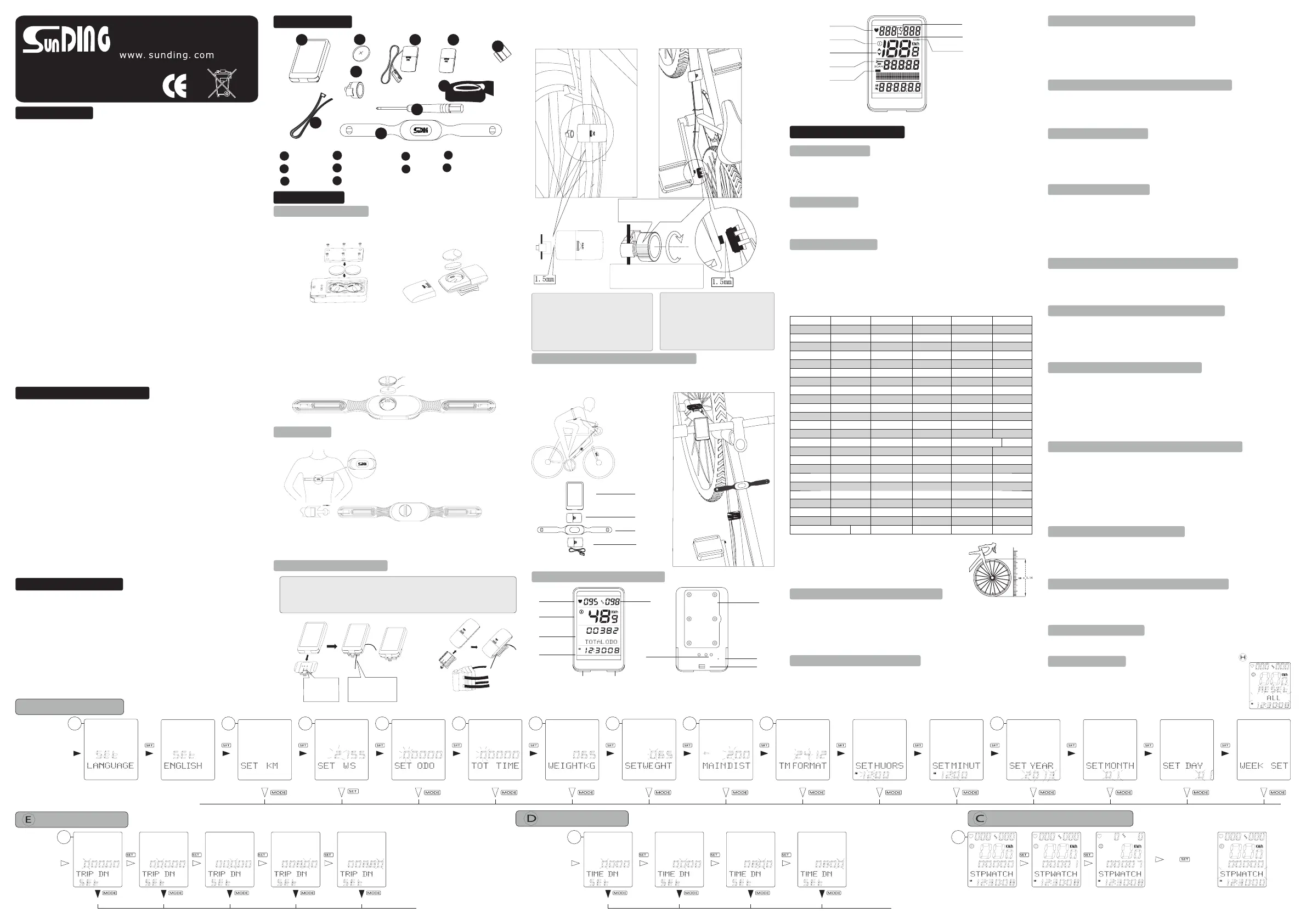
PARAMETER SETTINGS
-MULTI-LANGUAGE SETTING (CN / UK DE FR IT ES / / / / /
SE NL ) (Fig 1) /
-KM / M (Fig 2)
-CELSIUS / FAHRENHEIT
-WHEEL SIZE (Fig 3)
-INITIAL ODOMETER VALUE (KM / M) (Fig 4)
-INITIAL CHRONOMETER VALUE (Fig 5)
-METRIC / IMPERIAL SETTING (Fig 6)
-RIDER WEIGHT (Fig 7)
-MAINTENANCE DISTANCE (Fig 8)
-CLOCK (Fig 9)
-DATE (Fig 10)
-DISTANCE COUNTDOWN (Fig 11)
-TIME COUNTDOWN (Fig 12)
-MENU CYCLE (Fig 14)
-CHAINWHEEL / FLYWHEEL (Fig 15)
-HIDE MENU (Fig 44)
-PANORAMIC DISPLAY (Fig 45)
AUXILIARY MODE
-PANORAMIC DISPLAY MODE (Page 2, Figs 40, 41, 42)
-MENU CYCLE MODE (Fig 43)
-SPEED COMPARISON
-HIDE MENU MODE
-MAINTENANCE ALERT
-LOW BATTERY INDICATOR
-WIRELESS WAKE UP
-SMART BACKLIGHT
-REMOTE CONTROL
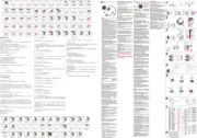
stopwatch Function Operation
Parameter Setting
Digital Adjust
Digital Adjust
TM DN Setting
Option Switching And Digital Adjustment
In TRIP DN
MODE ,press
the SET button
In TTM MODE ,
press the SET
button
Press the
SET button for 3
seconds in
ODO or TTM
MODE to enter
into Language
setting menu
TRIP DN Setting
press
for 3s
reset
Thread ties through
the slots under the
base to attach to
handlebar
Match base
alignment with
computer and
insert to attach
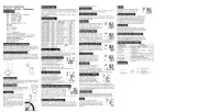
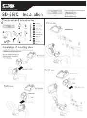
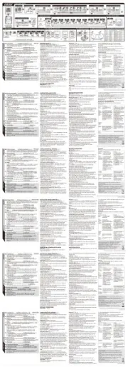
Computer Installation
Attach the computer to the handlebar and secure using included ties.
To check the installation, spin the front wheel with the computer in speed
mode and observe whether there is output on the computer screen.
Adjust sensor and magnet position if signal is weak or nonexistent.
*Dry, cold weather may interfere with heartbeat monitor functionality.
To resolve, wait for a few minutes. You can also put a few drops of
clean water on the heartbeat monitor conductor.
Chest Belt
* Attach belt so SunDing logo can be seen
from outside, right side up. The belt must
be placed over the heart, with no clothing
or other material separating it from the body.
Installation
*Computer battery installation: Open the battery cover. Install two
CR2032 batteries with positive poles facing battery cover. Replace
cover and tighten with screwdriver.
Battery Installation
*Speedometer and cadence sensor battery installation: Open the
battery cover on the bottom of the computer with a flathead screwdriver.
Install CR2032 battery with positive pole facing battery cover. Replace
cover and tighten with screwdriver.
*Chest belt installation: Open the battery cover. Install CR2032 battery
with positive pole facing battery cover. Replace and tighten cover by
turning right.
Heart Rate Monitor
Chest Belt
9
8
9
5
6
4
4
Computer
CR2032 Battery
Magnet
Cadence Sensor
Sensor
Multi-Magnet
Ties
2
2
1
7
7
3
3
5
6
Accessories
10
Screwdriver
10
1
8
Installation of
Speedometer
Installation
cadence of sensor
The magnet is designed for spokes
that are less than 2mm thick
Pass bicycle spokes through
the plastic hole on the
bottom of the magnet and
tighten to secure
Notice
Attach speedometer sensor to the front
fork using the ties. The computer and
sensor should be installed on the same
side of the fork, with distance between
them of less than 60cm. The arrow on
the sensor should point at the magnet.
Install magnet as shown in figure.
Distance between sensor and magnet
should be 1.5mm.
Install cadence transmitter on down tube
of frame, with fewer than 60cm separating
it from the computer. Attach the cadence
sensor to the rear fork. Insert the magnet
into the pedal hole, with distance between
magnet and transmitter of less than
1.5mm. Secure line between transmitter
and sensor with ties.
Position of Computer and Accessories
When riding, the computer and accessories should be parallel to one
another. The diagram below shows the positioning and distance
between the computer, speedometer, and cadence sensor, which
should be less than 60 cm.
Parallel
Parallel
Parallel
Parallel
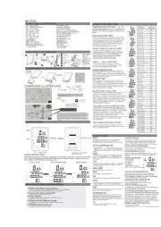
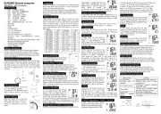
Computer Function Display Area
Accessories should be positioned
parallel to computer, as shown
Front
Back
CADENCE
SPEED
HEART RATE
CLOCK
FUNCTION
SET
MODE
CONTACT
BATTERY
COVER
SLOT
PRESSURE
HOLE
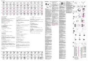
MAINTENANCE DISTANCE SETTING(Figure 8)
Distance Countdown Setting mode (Figure 11)
Time Countdown Setting mode (Figure 12)
Menu Hidden Setting (Figure 44)
In any mode, hold the MODE button for 3 seconds to enter Menu Hidden
mode. Press SET button to enter Hide Total Odometer setting. When
“On” is flashing, the Total Odometer is shown. When “Off” is flashing,
the Total Odometer is hidden. Please see diagram on back for
additional details.
Temperature Setting
Clock Setting (Figure 9)
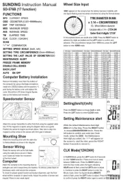
Wheel Size Setting
Parameter Settings
KM / M Setting
Language Setting
Initial Odometer Setting (Figure 4)
Riders Weight Setting (Figures 6, 7)
Initial Time Setting (Figure 5)
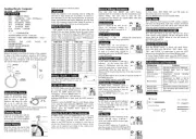
Tire Size Chart (in mm)
If you are unable to locate your tire size on
this chart, you can use the method shown
to the right to measure the time diameter
and calculate the tire circumference.
Circumference = diameter x 3.14
When the Initial Value of Odometer setting mode is selected, press the
MODE button to enter it. To adjust the selected figure, press the MODE
button, and press the SET button to confirm your value and move to the
next field. Press the SET button once finished with Initial Odometer
Setting to move onto the Initial Time setting.
When the Initial Time setting mode is selected, press the MODE button to
enter it. To adjust the selected figure, press the MODE button, and press
the SET button to confirm your value and move to the next field. Value
ranges from 0 to 99,999 hours. Press the SET button once finished with
Initial Time setting to move onto Riders Weight setting.
When the Riders Weight setting mode is selected, press the MODE to
set weight measurement unit (KG or LB) and press SET button to
move to set weight. Use the MODE button to adjust flashing number
for weight, and press SETto confirm and advance to next digit. The
default weight is 65 KG, any value from 0 – 299 entered. Press MODE
button to confirm value and enter into Clock setting mode.
In Temperature Setting mode, hold SET button for 3 seconds to
toggle between Celsius and Fahrenheit.
Press MODE button to select KM or M, and press Set button to confirm
and enter into Wheel Size Setting.
In Wheel Size Setting mode, The default is 2155 mm.select wheel
circumference based on below chart. Press the MODE button to
change each figure, and press SET to confirm and move on to next
setting. Afterwards, press SET to enter into Odometer Setting mode.
To set language, remove and reinstall battery, or hold SET button for 3
seconds in ODO or TTM Mode. Select language using MODE button,
and press SET button to confirm and enter into KM / M Setting.
When “24” flashes in Clock mode, press MODE button to toggle between
12 and 24 hour time format. Press SET to confirm and move to Hour
setting. Press MODE button to adjust flashing Hour value, and press SET to
confirm and move to Minute setting. Press MODE button to adjust flashing
Minute value, and press SET to confirm and enter into Date setting.
In Distance Countdown Setting mode, hold the SET button for 3 seconds,
then use the MODE button to adjust the mileage value. Press SET again
to move to the next value. Once correct value has been input, pressSET
button to confirm and return to Distance Countdown Setting mode.
In Time Countdown Setting mode, hold the SET button for 3 seconds, then use
the MODE button to adjust the Hour value. Press SET again to move to the
Minute value. Once correct value has been input, press SET button to confirm
and move to the Second value. Once correct value has been input, press SET
button to confirm and return to Time Countdown Setting mode.
Date Setting (Figure 10)
In Year Setting mode, press MODE button to adjust year, then press SET
button to confirm and move to Month Setting mode. In Month Setting
mode, press MODE button to adjust month, then press SET button to
confirm and move to Day Setting mode. In Day Setting mode, press
MODE button to adjust the date, and press SET to move to Week Setting
mode. In Week Setting mode, press MODE button to adjust week, and
press SET to confirm and move to Distance Countdown Setting mode.
Panoramic Display Setting mode (Figure 45)
In Panoramic Display Setting mode, hold SET button for 3 seconds to
toggle Panoramic Display.When the digit on the first row is flashing, press
the MODE button to adjust it.Press SET button to confirm and move
on to the next row. Please see diagram on back for additional details.
Menu Cycle Setting mode (Figure 14)
In Menu Cycle Setting mode, press the SET button for 3 seconds to enter
Menu Cycle Setting. Press SET button again to enter Total Odometer
Cycle Setting. When “Out” is flashing, it represents the Total Odometer
withdrawn from the Cycle mode. Press the MODE button toggle “Join”
mode. When “Join” is flashing, it represents the Total Odometer added
to the Cycle mode.Press the SETbutton to confirm and enter into Trip
Cycle Setting. Please see diagram on back for additional details.
Panoramic Display mode may not be exited from this menu.
Chainwheel / Flywheel Setting mode (Figure 15)
In Cadence Gear Ratio mode, hold SET button for 3 seconds to enter into
Flywheel Parameter Setting. The small digits at the top of the display
represent the flywheel parameters. The number of the flywheel is
displayed in descending order. If there is no flywheel, the display will
show 0. The small digits at the lower part of the display represent the
chainwheel parameters. The number of chainwheel is displayed in
descending order; the display will show 0 if there is no chainwheel.
Please see diagram on back for additional details.
In Clear Signal Data mode, hold SET button for 3
seconds to clear all signal data.
Clear Signal Data
IN MAINTENANCE DISTANCE mode, press the MODE button to
change the number of digital, and press the SET button confirm and
advance. The default weight is 200,and its ranges from 200 to 899KM.
Press the MODE button to confirm and enter into CLOCK SETTING.
Date cleared
LOW BATTERY INDICATOR
HEART RATE DISPLAY
CADENCE CONTRAST
CADENCE SIGNAL
SPEED COMPARISON
MAINTENANCE
REMINDERS
PANORAMIC
DISPLAY
ROTATION ANIMATION
CR2032
Battery Cover
12×1.75 935
12×1.95 940
14×1.50 1020
14×1.75 1055
16×1.50 1185
16×1.75 1195
16×2.00 1245
16×1-1/8 1290
16×1-3/8 1300
17×1-1/4 1340
18×1.50 1340
18×1.75 1350
20×1.25 1450
20×1.35 1460
20×1.50 1490
20×1.75 1515
20×1.95 1565
22×1-3/8 1770
22×1-1/2 1785
24×1.75 1890
24×2.00 1925
24×2.125 1965
24×1(520) 1753
24×/34Tubular 1785
24×1-1/8 1795
24×1-1/4 1905
26×1(599) 1913
26×1.25 1950
26×1.40 2005
26×1.50 2010
26×1.75 2023
26×1.95 2050
26×2.10 2068
26×2.125 2070
26×2.35 2083
26×3.00 2170
26×1-1/8 1970
26×1-3/8 2068
26×1-1/2 2100
26×7/8 1920
650×20C 1938
650×23C 1944
650×25C 1952
650×38A 2125
650×38B 2105
27×1(630) 2145
27×1-1/8 2155
27×1-1/4 2161
27×1-3/8 2169
27.5×1.50 2079
27.5×1.95 2090
27.5×2.1 2148
27.5×2.25 2182
700×18C 2070
700×19C 2080
700×20C 2086
700×23C 2096
700×25C 2105
700×28C 2136
700×30C 2146
700×32C 2155
700Tubular 2130
700×35C 2168
700×38C 2180
700×40C 2200
700×42C 2224
700×44C 2235
700×45C 2242
700×47C 2268
29×2.1 2288
29×2.2 2298
29×2.3 2326