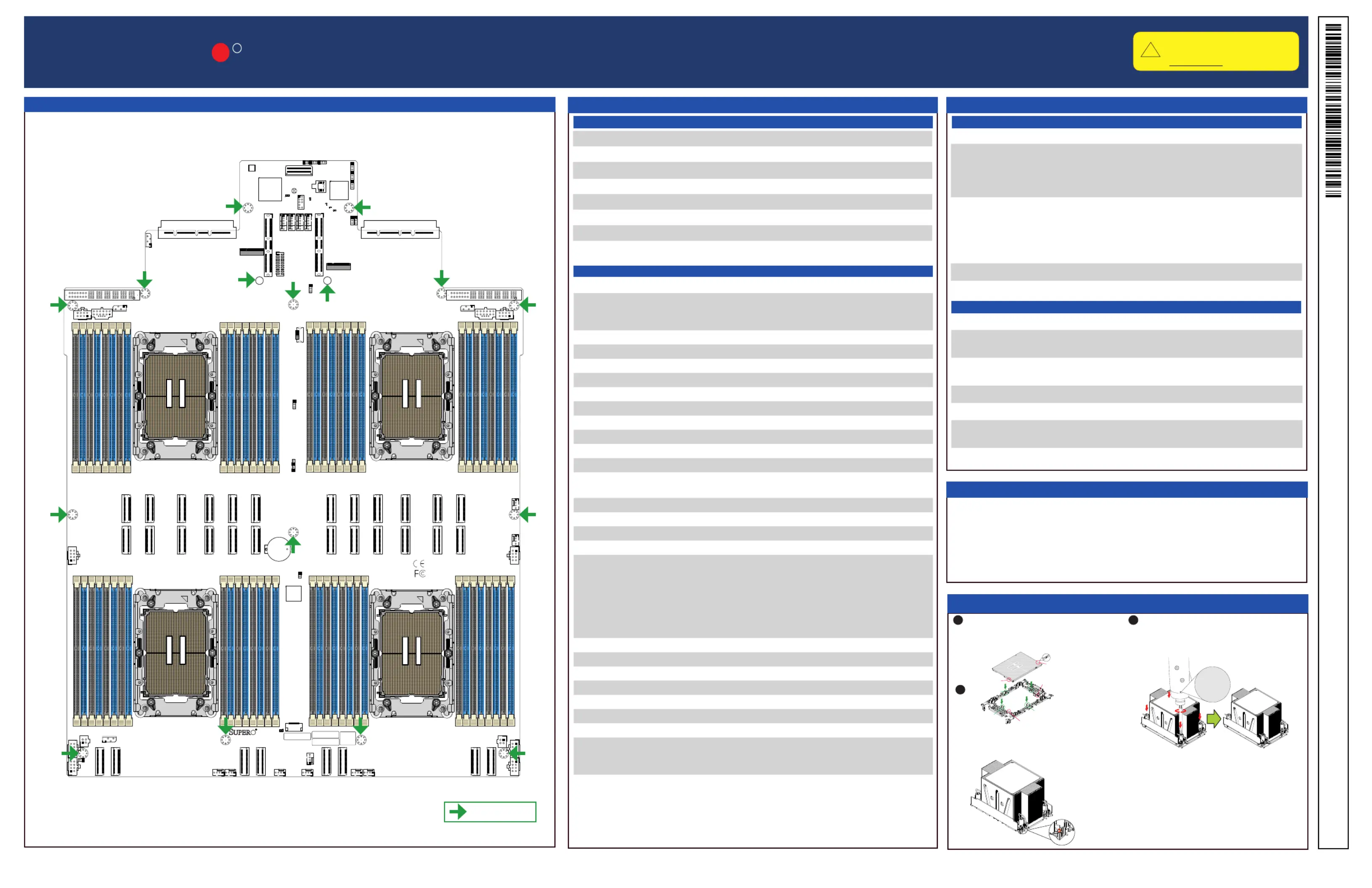
Supermicro X14QBH+ Manual


Læs gratis den danske manual til Supermicro X14QBH+ (1 sider) i kategorien Ikke kategoriseret. Denne vejledning er vurderet som hjælpsom af 2 personer og har en gennemsnitlig bedømmelse på 4.7 stjerner ud af 1.5 anmeldelser. Har du et spørgsmål om Supermicro X14QBH+, eller vil du spørge andre brugere om produktet?

Side 1/1
© 2025 Supermicro Computer Inc. All rights reserved. Reproduction of this document whether in part or in whole is strictly prohibited without Supermicro's written
consent. All Trademarks are property of their respective entities. All information provided is deemed accurate at the time of printing; however, it is not guaranteed. MNL-2720-QRG-100
S
UPERMICR
R
Package Contents
One Supermicro Motherboard
One Quick Reference Guide
X14QBH Quick Reference Guide
lead, known to the State of California to cause cancer and birth
defects or other reproductive harm. For more information, go
to www.P65Warnings.ca.gov.
!
DESIGNED IN USA
BIOS LICENSE
MAC CODE
MAC CODE
A C
A C
C
A
C
C
A
BAR CODE
X14QBH+
REV:1.00
B1
JBT1
JPGW3
FP1
MH11
MH8
MH3
MH12
MH4
MH6
MH2
MH7
MH16
MH15
MH1
MH10
MH5
PSU2
USB2 (3.0) JTPM1
M.2_MH1
FP2
JMD2
JMD1
FAN12
FAN11
FAN10_STBY
FAN9
JL1
JSPD1
JRU1J5
J4
JLC1
JTP1
JPG1
JPME2
JWD1
LED4
LED7
LED3
JFAN1
JIPMB1
JPWR4
JPWR3
JPWR6
JPWR5
JPWR7
JPWR8
JPGW4
LED1
LED2
LED6
FAN_STBY
FAN1
FAN2
FAN3
FAN4
FAN5
FAN6
FAN8
FAN7
P3_PCIe6A_VPP
P3_PCIe6B_VPP
P3_PCIe5B_VPP
P3_PCIe5A_VPP
P4_PCIe6A_VPP
P4_PCIe6B_VPP
P4_PCIe5A_VPP
P4_PCIe5B_VPP
P2_PCIe1B_VPP
P2_PCIe4AP3_PCIe3A_VPP
P3_PCIe3B_VPP P2_PCIe4B
P1_PCIe3BP4_PCIe4B
P1_PCIe3AP4_PCIe4A
P1_PCIe1A_VPPP4_PCIe1B
P1_PCIe1B_VPPP4_PCIe1A
P1_PCIe4AP4_PCIe3A
P1_PCIe4BP4_PCIe3B
JPWR1
JPWR2
JBAT1
MH14
MH13
JSKUID1
JSKUID2
J8
JSKUID3
P2_PCIe3B
P2_PCIe3A
P2_PCIe1A_VPP
P2_PCIe4B_VPP
P2_PCIe4A_VPP
P2_PCIe1B
P2_PCIe1A
IO1: BMC LAN/USB0/1(3.0)/DP
P4_DIMMD1
P4_DIMMC1
P4_DIMMD2
P4_DIMMC2
P4_DIMMB2
P4_DIMMB1
P4_DIMMA2
P4_DIMMA1
P4_DIMME2
P4_DIMME1
P4_DIMMF1
P4_DIMMF2
P4_DIMMG1
P4_DIMMG2
P4_DIMMH1
P4_DIMMH2
P3_DIMMH1
P3_DIMMG1
P3_DIMMH2
P3_DIMMF1
P3_DIMMG2
P3_DIMME1
P3_DIMMF2
P3_DIMME2
P3_DIMMA2
P3_DIMMA1
P3_DIMMB1
P3_DIMMB2
P3_DIMMC1
P3_DIMMC2
P3_DIMMD1
P3_DIMMD2 P2_DIMMH2
P2_DIMMH1
P2_DIMMG2
P2_DIMMG1
P2_DIMMF2
P2_DIMMF1
P2_DIMME2
P2_DIMME1
P2_DIMMA2
P2_DIMMB2
P2_DIMMA1
P2_DIMMC2
P2_DIMMB1
P2_DIMMD2
P2_DIMMC1
P2_DIMMD1
P1_DIMMD1
P1_DIMMC1
P1_DIMMD2
P1_DIMMB1
P1_DIMMC2
P1_DIMMA1
P1_DIMMB2
P1_DIMMA2
P1_DIMME1
P1_DIMME2
P1_DIMMF1
P1_DIMMF2
P1_DIMMG1
P1_DIMMG2
P1_DIMMH1
P1_DIMMH2
CPU4
CPU3
CPU1
CPU2
J7
P1_AIOM PCIe 5.0 x16
P2_AIOM PCIe 5.0 x16
P1_HIO_R1_PCIe 5.0 x16
P2_HIO_L1_PCIe 5.0 x16
PSU1
J6
JPGW2JPGW1
MH9
Jumper Description Default Setting
JBT1 CMOS Clear Open (Normal)
JPG1 VGA Enable/Disable Pins 12 (Enabled)
JPME2 ME Manufacturing Mode Pins 12 (Normal)
JPT1 Onboard TPM Enable/Disable Pins 12 (Enabled)
JRU1 UID LED/System Reset Jumper Pins 12 (UID LED)
JWD1 Watchdog Timer Pins 12 (Reset)
Connector Description
FAN1FAN12
FAN_STBY
FAN10_STBY
FAN1FAN9, FAN11FAN12: Fan Headers
FAN_STBY: 4-pin STBY Fan Header
FAN10_STBY: 6-pin STBY Fan Header
FP1 Front Control Panel Header
FP2 VGA and USB3/4 (2.0)
IO1 BMC LAN/USB0/1 (3.0)/DP
J5 NMI Switch
J6 Sideband Signal Connector for PDB1
J7 Sideband Signal Connector for PDB2
J8 VRM Programming Write Protect
JL1 Chassis Intrusion Header
JBAT1 Extended CMOS Battery
JFAN1 FAN_PMB
JGPW1JGPW4
JGPW1: +12 V PWR7, JGPW2: GPU_PWR1
JGPW3: GPU_PWRS2, JGPW4: +12 V_PWR8
JIPMB1 4-pin BMC External I
2
C Header
JLC1 Liquid Cooling Leakage Detect
JMD1 M.2-C1 PCIe 4.0 p1-x4 Slot
JMD2 M.2-C2 PCIe 4.0 p1-x4 Slot
JPWR1JPWR8
JPWR1JPWR2: 4-pin Power Headers for backplane devices
JPWR3 (+12 V_PWR1): 8-pin Backplane Power Connector 1
JPWR4 (+12 V_PWR2): 8-pin Backplane Power Connector 2
JPWR5 (+12 V_PWR3): 8-pin Backplane Power Connector 3
JPWR6 (+12 V_PWR4): 8-pin Backplane Power Connector 4
JPWR7 (+12 V_PWR5): 8-pin Backplane Power Connector 5
JPWR8 (+12 V_PWR6): 8-pin Backplane Power Connector 6
JTPM1 Trusted Platform Module/Port 80 Connector
M.2_MH1 M.2 Mounting Hole
MH1MH16 Motherboard Mounting Holes
P1_AIOM PCIe 5.0 x16 Advanced I/O Module (AIOM) PCIe 5.0 Slot supported by CPU1
P2_AIOM PCIe 5.0 x16 Advanced I/O Module (AIOM) PCIe 5.0 Slot supported by CPU2
P1_HIO_R1_PCIe 5.0 x16 PCIe 5.0 p1-x16 Hybrid Slot for right riser card supported by CPU1
P2_HIO_R1_PCIe 5.0 x16 PCIe 5.0 p1-x16 Hybrid Slot for left riser card supported by CPU2
P1_PCIe1A_VPP/P1_PCIe1B_VPP
P1_PCIe3A/P1_PCIe3B
P1_PCIe4A/P1_PCIe4B
PCIe 5.0 p1-x8 Slots by CPU1
P2_PCIe1A_VPP/P2_PCIe1B_VPP
P2_PCIe3A/P2_PCIe3B
P2_PCIe4A/P2_PCIe4B
PCIe 5.0 p1-x8 Slots by CPU2
Connectors
Jumpers and Connectors
Motherboard Layout and Features
Jumpers
= mounting hole
Processor and Memory Support
The X14QBH+ motherboard supports the Intel
®
Xeon 6700P-Series scalable pro-
cessors with a Thernal Design Power (TDP) of 165 W to 350 W in an LGA 4710
E2 socket.
The X14QBH+ motherboard supports up to 16 TB of ECC DDR5 3DS RDIMM with
speeds of up to 6400 MT/s in 64 DIMM slots.
LED Description Status
LED1 CPU2 Power Good Status LED
Red: Power is not ready
Dimmed: Power is ready
LED2 CPU3 Power Good Status LED
Red: Power is not ready
Dimmed: Power is ready
LED3 BMC Heartbeat LED Blinking Green: BMC Normal
LED4 BMC Heartbeat Failure LED Solid Red: BMC Failure
LED6 CPU4 Power Good Status LED
Red: Power is not ready
Dimmed: Power is ready
LED7 Motherboard Power On LED Solid Green: Power On
Processor and PHM Installation
1
1
1
2
1
3
Assemble the processor carrier assembly by
aligning and placing one end of the processor
into the latch marked A, and place the other
To form the processor heatsink module (PHM),
mount the processor carrier assembly onto the
heatsink and snap into place.
After assembling the PHM, mount it onto the
CPU socket. With a T30 bit torque driver set
to a force of 8.0 in-lbf (0.904 N-m), gradually
tighten the four screws.
The CPU carriers XCC (SKT-1543H-0000-FXC) and
HCC/LCC (SKT-1544H-0000-FXC) are included in
the shipping package.
1
2
3
4
B
A
b
a
Processor Key
Processor Key
Processor Key
Processor Key
Latch
Latch
Latch
Latch
3
4
5
6
7
8
9
1
0
1
1
in-lbf
8.0
0.904
N-m
Connectors and LED Indicators
LED Indicators
Connectors
Connector Description
P3_PCIe1A/P3_PCIe1B
P3_PCIe3A_VPP/P3_PCIe3B_VPP
P3_PCIe4A_VPP/P3_PCIe4B_VPP
P3_PCIe6A_VPP/P3_PCIe6B_VPP
PCIe 5.0 p1-x8 Slots by CPU3
P4_PCIe1A/P4_PCIe1B
P4_PCIe3A/P4_PCIe3B
P4_PCIe4A/P4_PCIe4B
P4_PCIe5A_VPP/P4_PCIe5B_VPP
P4_PCIe6A_VPP/P4_PCIe6B_VPP
PCIe 5.0 p1-x8 Slots by CPU4
PSU1, PSU2 Power Supply Unit 1, Power Supply Unit 2
USB2 USB 3.0 Header
Download Drivers and Utilities: https://www.supermicro.com/wdl/driver/
Refer to the Component Installation section of the user manual for information on jumpers, connectors, LED Indicators, memory support, and processor installation instructions.


Produkt Specifikationer

Mærke: Supermicro
Kategori: Ikke kategoriseret
Model: X14QBH+

Har du brug for hjælp?

Hvis du har brug for hjælp til Supermicro X14QBH+ stil et spørgsmål nedenfor, og andre brugere vil svare dig