Tempo FI-100-KIT Manual
Tempo
Kabler til computere og periferiudstyr
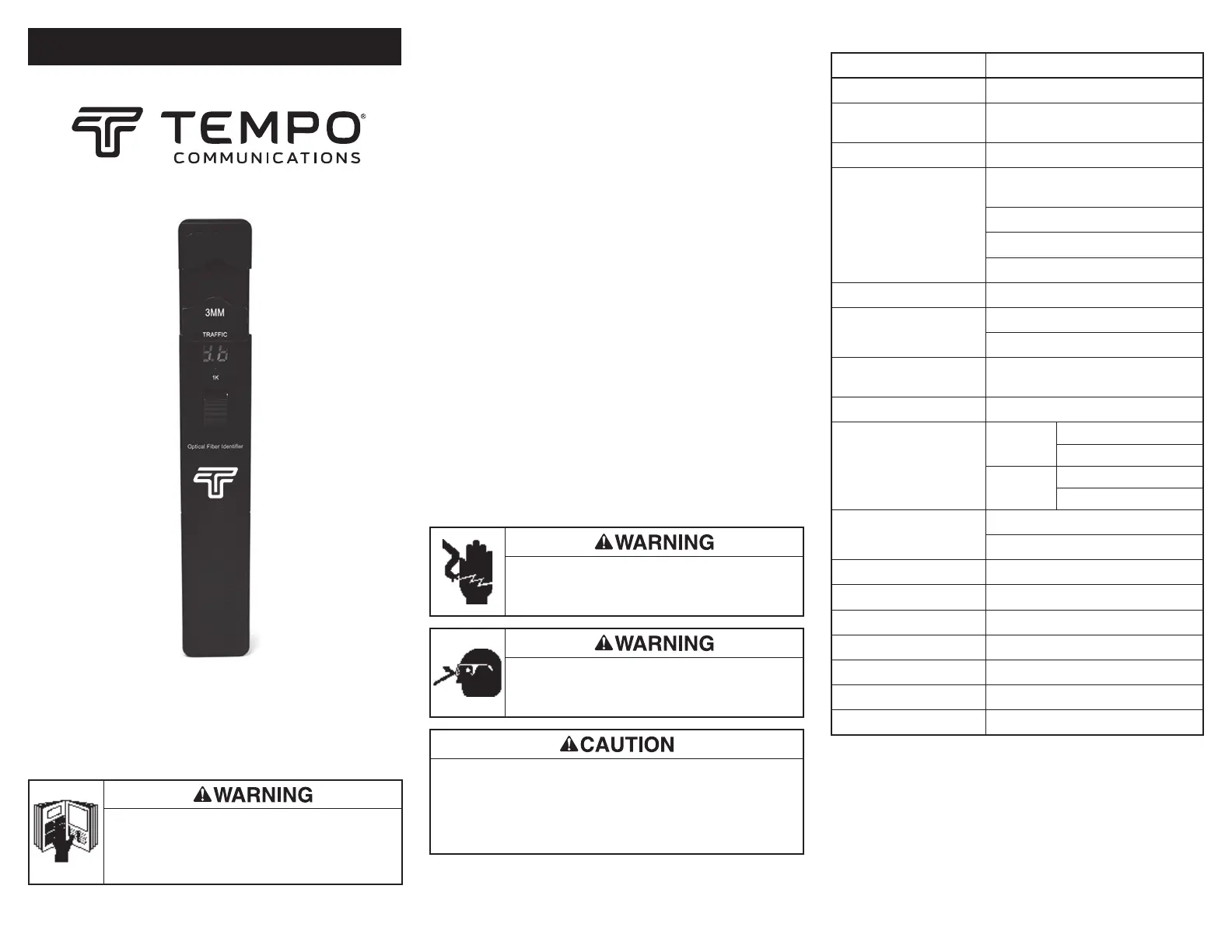
FI-100-KIT
| Mærke: | Tempo |
| Kategori: | Kabler til computere og periferiudstyr |
| Model: | FI-100-KIT |
| Bredde: | 30.5 mm |
| Dybde: | 27 mm |
| Højde: | 196 mm |
| Vægt: | 195 g |
| Produktfarve: | Sort |
| Batteriteknologi: | Alkaline |
| Opbevaringstemperatur (T-T): | -25 - 70 °C |
| Driftstemperatur (T-T): | -10 - 60 °C |
| Certificering: | CE, FCC, RoHS, EAC |
| Batteritype: | AAA |
| Antal understøttede batterier: | 2 |
| Bæredygtighedscertifikater: | CE, RoHS |
| Overholdelse af bæredygtighed: | Ja |
| Bølgelængde område: | 800 - 1700 nm |
| Kalibrerede bølgelængder: | 800 nm |
Har du brug for hjælp?
Hvis du har brug for hjælp til Tempo FI-100-KIT stil et spørgsmål nedenfor, og andre brugere vil svare dig
Kabler til computere og periferiudstyr Tempo Manualer
4 Oktober 2025
Kabler til computere og periferiudstyr Manualer
- Audio-Technica
- Tributaries
- Renkforce
- Hama
- Abus
- Goobay
- EK Water Blocks
- Vantec
- Black Box
- Alogic
- Opticis
- I-Tec
- Pyle
- Fresh 'n Rebel
- Elgato
Nyeste Kabler til computere og periferiudstyr Manualer

10 Januar 2026

15 December 2025

10 December 2025

10 December 2025

29 November 2025

13 November 2025

11 November 2025
6 November 2025

3 November 2025
3 November 2025