Vemer S.p.A.
I - 32032 Feltre (BL) • Via Camp Lonc, 16
Tel +39 0439 80638 • Fax +39 0439 80619
e-mail: info@vemer.it - web site: www.vemer.it
User manual
GSM COMMUNICATION INTERFACE
Read all instructions carefully
Tlc-solar is a system for the remote control of photovoltaic systems by sending text
messages or ring tones to certified users.
The heart of the system is made up of GWI solar which compares the signal coming
from the produced energy meter on the system and that coming from the radiation
sensor to check if production complies with the radiation conditions, thus enabling any
malfunctions to be found in time. Any fall in production is automatically communicated
by the system by sending text messages to the selected users. Furthermore, GWI solar
has another input available for connecting a burglar alarm and two outputs which can be
activated manually or following an alarm.
SAFETY WARNINGS
During the installation and operation of the device observe the following instructions:
1) The instrument must be installed by a qualified person
2) The instrument must be installed and activated in compliance with current electric
systems standards
3) After installation, inaccessibility to the connection terminals without appropriate tools
must be granted
4) Do not use the instrument for purposes other than indicated
5) The device must be installed in a electric closed panel well protected
6) A two-pole disconnect device shall be provided as part of the building installation
7) A protection device against over-currents should be installed in the electrical system,
upstream of the device
8) Carefully respect the wiring diagrams to install the instrument
9) Before accessing the connection terminals, verify that the leads are not live
10) Do not power or connect the instrument if any part of it is damaged
11) The use of a GSM device can cause interference with the functioning of electronic devices
non-screened from radiofrequency signals (electromedical devices, pacemakers, hearing
aids etc.)
12) In case of fault, do not service the device yourself but contact the after-sales service
13) The instrument is aimed for use in place with over-voltage category III and pollution
degree 2, as per standards EN 60730-1.
Code Model Description
KT018000 Tlc-solar 230 Kit telecontrol for single-phase systems up to 15 kW
KT018500 Tlc-solar 400 Kit telecontrol for three-phase systems up to 69 kW
KT021500 Tlc-solar 400TA Kit telecontrol for three-phase systems up to 690 kW
The Tlc-solar is made up of:
– GWI solar control unit (code VE326500)
– radiation sensor (code VE327300)
– TMC 10/12 transformer (code VN314100)
– ADR-D 230 D63 energy meter (code VE035200) (single-phase systems) or
ENERGY-400 D90 ENERGY-400D PWRi (code VN984100) (three-phase 69kW systems) or
(code VE120200) (three-phase 690kW systems)
INSTALLATION
• Preparation
Disable the pin code request from the sim card which will
be inserted into the GWI solar.
Insert the sim card into the slot (type push-push). The
direction of insertion provides that the bevel of the sim
card goes inside in the left.
Note: the rechargeable sim needs a periodical
minimum top-up (usually once a year) in order to
be valid. Check with your operator about the renewal mode.
Note. The sim card insertion and removal operations should be carried out with
the instrument switched off and not powered up (please see the relative chapter
for switching off the instrument).
• Wiring
– Attach the radiation sensor near the photovoltaic panels with the same inclination and
connect it to the analog input of the GWI solar (the white/black wire to terminal 14, the
black one to terminal 12).
Caution: the sensor must be positioned so that the solar rays do not hit it before they hit
the panels, in order to avoid false alarms being sent, for example, at dawn.
– connect the energy meter down from the solar production inverter, and connect the pulse
output meter at input 1 of the GWI solar (DIG1 - terminals 10 and 13)
– connect any burglar system (presence sensors, microswitches, ...) at digital input 2
GWI solar (DIG2 - terminals 11 and 13)
– connect the transformer to the GWI solar and the network voltage.
For a detailed description of the connections, please see the diagram “Connection diagram”.
Once the kit has been powered up, the led of the GWI solar relating to the device status
will remain on steady green for around 30 seconds, this will end when it starts blinking green
once a second, signalling the correct reception of the gsm network. If this should not be the
case, please see the overview “Device state”.
• Basicconfiguration
Consists in defining the admin number, which has full control of the system (usually for the
owner) to whom alarm messages are sent
MEMORISING ADMINISTRATIVE NUMBERS
– press the key of the GWI solar for 5 seconds until the led starts blinking red/green “1”
alternately
– carry out a ring tone with the number which you want to set as admin number.
The caller will receive a confirmation text message that this has taken place.
Note: after having set the admin number, the GWI solar will carry out a self-
calibration procedure, during which time it analyses all the parameters of the
system where it is installed. To carry out this operation the GWI solar needs a few
hours of sunshine.
At the end, the admin number will receive a text message and from then on, it
will begin to monitor the produced energy.
OPERATION
• Defaultsettings
The factory settings for the kit provide for the admin number to receive a series of text
messages:
– send a monthly text message to the administrator with the value of produced energy
– send a text message containing the value of produced energy and instantaneous power
following a ring tone
– forward messages destined to the GWI solar and not recognisable as commands (for
example a text message from a telephone service provider) to the administrator
Furthermore a text message is sent to the administrator in cases of:
– radiation sensor malfunction alarm
– no meter pulses alarm
– production below threshold alarm
– no electrical network or buffer battery flat alarm
For each of the alarms listed above, an alarm return text message is sent.
By default the pulse weight received from input DIG1 is 0.1 kWh (modifiable).
• Advancedconfiguration
In this phase it is possible to add other telephone numbers as well as the administrator's
(staff numbers) where alarm signals will be sent, by choosing for each number which type of
alarm to send.
Furthermore, it is possible to modify the automatic forwarding plan for messages with
planned set times or activate automatic switching function for an output following a specific
alarm condition.
STRUCTURE OF A COMMAND TEXT MESSAGE
The general structure of a text message is as follows:
[password] [separator] [command] [separator] [parameter1] [separator]..[parameterNo.]
where:
[password] numerical field of a maximum of 8 figures
[separator] comprised of one or more space characters
[command] command recognised by the device
[parameter..] series of parameters relative to the command
The password field may be omitted if the command is given by a registered
number. Several commands may be included in one text message. In this case, the
commands executed will only be those whose reply is contained in a standard
text message (160 characters). To enter numbers with the decimal separator,
you need to use a full stop.
The structure of a reply to a command is similar to the command itself, with the
addition of the “=” symbol to indicate the current status. For example:
OUTKEY BLOCK OUTKEY=BLOCK
MODIFY PULSE WEIGHTS (for admin only)
By default the pulse weight that the GWI solar receives from the energy meter
is 0.1 kWh. If it is necessary to modify this value use the command:
[pulse weight] whereWIMP
[pulse weight] new value to be given to a pulse
In the case of decimal values, use a decimal point as a separator.
To read the current value use the command WIMP with no parameters.
For example:
WIMP 1 gives the value 1.00 kWh to each pulse
WIMP 0.1 gives the value 0.10 kWh to each pulse
WIMP restores the current weight of the pulse
MEMORISINGSTAFFNUMBERS(foradminonly)
It is possible to create a telephone book containing up to 10 telephone numbers (staff
numbers) which can:
– receive text message (or ring tone) in case of alarms
– receive text message with the produced energy and the instantaneous power
following a ring tone
– receive text message following a scheduled event.
The staff numbers are identified progressively from 1 to 10.
The first 5 staff numbers are already associated by default to 5 well defined alarm
situations (please see “Alarms management”) even if they can be modified.
To add a staff number:
– send the following command from the admin number:
STAFF [index] [telephone number] where,
[index]
position in the staff telephone book where the new number is saved
[telephone number]
number to be added to the telephone book
For example, to insert the staff number 392123445 in position 4:
STAFF 4 392123445
It is also possible to enter several staff numbers using one command only:
For example, if you want to insert the numbers 044177458, 392123445 and 12345678 in
positions 2, 4, and 7:
STAFF 2 044177458 4 392123445 7 12345678
To cancel a staff number, use the word NULL.
For example, if you want to cancel the staff number 4, leaving the position in the
telephone book empty:
STAFF 4 null
To have a complete overview of the telephone book write STAFF without parameters.
Note: the admin number is inserted by default as staff number position 1.
ALARMS MANAGEMENT
The possible alarm sources are reported in the following table:
Table 1
Type of alarm Alarm description
DIG2 Alarm from digital input 2
RDIG2 Alarm return from digital input 2
LOWBAT Low battery alarm
POWERF No network alarm
RPOWERF Alarm return for no mains
SCHED Message for periodic forwarding
LUX Radiation sensor malfunction
RLUX Alarm return radiation sensor
IMP Inverter malfunction
RIMP Alarm return inverter malfunction
DELTA Alarm energy production lower than predicted
RDELTA Alarm return energy production
POK Production exceeds the threshold defined with SETPOK
RPOK Alarm return energy production above the threshold
It is possible to define which types of alarms are sent to each staff number and in which
format (text message or ring tone). The first 5 staff numbers are set as follows:
Table 2
Number ModeCommunications received
STAFF 1 Each alarm event
Text message
STAFF 2 Scheduled event only: SCHED
Text message
STAFF 3 Alarms only: LUX/RLUX, IMP/RIMP, DELTA/RDELTA
Text message
STAFF 4 Burglar alarm only: DIG2/RDIG2
Text message
STAFF 5 No electrical network only: POWERF/RPOWERF, LOWBAT
Text message
Mod. Tlc-solar
V3IS00546-020-122013
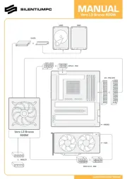
CONNECTION DIAGRAM
GWI solar TECHNICAL CHARACTERISTICS
GWI solar DEVICE STATUS
• Power supply: 12V AC from TMC 10/12 as shown in the diagram
• Absorption: 100mA max
• Output
- two bistable relays with change-over contact
− power circuit breaker: 8(5)A / 250V AC
• Signalling LEDs:
- Two red leds for output relay status signalling
- Two green leds for digital input status signalling
− Multicolour leds for device status signalling
• GSM Quad Band module (900-950-1800-1900 MHz)
• SMA-F connector for external antenna provided with 3 m long cable
• Working conditions: 0÷50 °C / 10÷90% non-condensing
• Degree of protection: IP40
• Insulation class: II
• Container: 4 DIN modules
• Backup battery capacity: approximately 1 hour
The device status is signalled by the led :
SWITCHED OFF no power supply to device
RED BLINKING sim card not inserted or pin active
RED STEADY insufficient gsm field
GREEN STEADY initialising instrument/network search
GREEN BLINKING gsm network connection
GREEN BLINKING VELOCE command (ring tone or text message) incoming
GREEN/RED BLINKING active programming mode
YELLOW BLINKING gsm network connection but battery flat
QUICKLY BLINKING RED modem error or failure (if still flashing)
Note: blinking = 1 lamp / second
quickly blinking = 5 lamps / second
kW/h kW/h
Generator
panel
radiation
sensor
Produced energy
unidirectional meter
Bidirectional produced/absorbed
energy meter
Inverter
General panel
Three-phase network
max 690 kW
Three-phase network
max 69 kW
Single-phase network
max 15 kW
sensore +
sensore –
GWI SOLAR
GWI SOLAR
burglar alarm
anti teft
anti teft
TMC 10/12GWI SOLARENERGY-400D PWRi
L1 L2 L3N
L3
L1
L2
I1 I2 I3
N
ADR-230 D63
N
L1
ENERGY-400 D90
N
L3
L1
L2
L1 L2 L3N
230 V ~
12 V ~
ENERGIA +
ENERGIA –
ENERGIA +
ENERGIA –
ENERGIA +
ENERGIA –
ENERGIA +
ENERGIA –
sensore +
sensore –
OUT 1
OUT 2
1 kWh / imp 0,1 kWh / imp 0,1 kWh / imp