Watts 800M4-QT-FZ Manual


Læs gratis den danske manual til Watts 800M4-QT-FZ (12 sider) i kategorien Ikke kategoriseret. Denne vejledning er vurderet som hjælpsom af 3 personer og har en gennemsnitlig bedømmelse på 4.9 stjerner ud af 2 anmeldelser. Har du et spørgsmål om Watts 800M4-QT-FZ, eller vil du spørge andre brugere om produktet?

Side 1/12
RP/IS-800M4
Installation, Maintenance, and Repair Manual
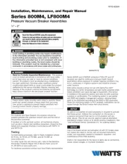
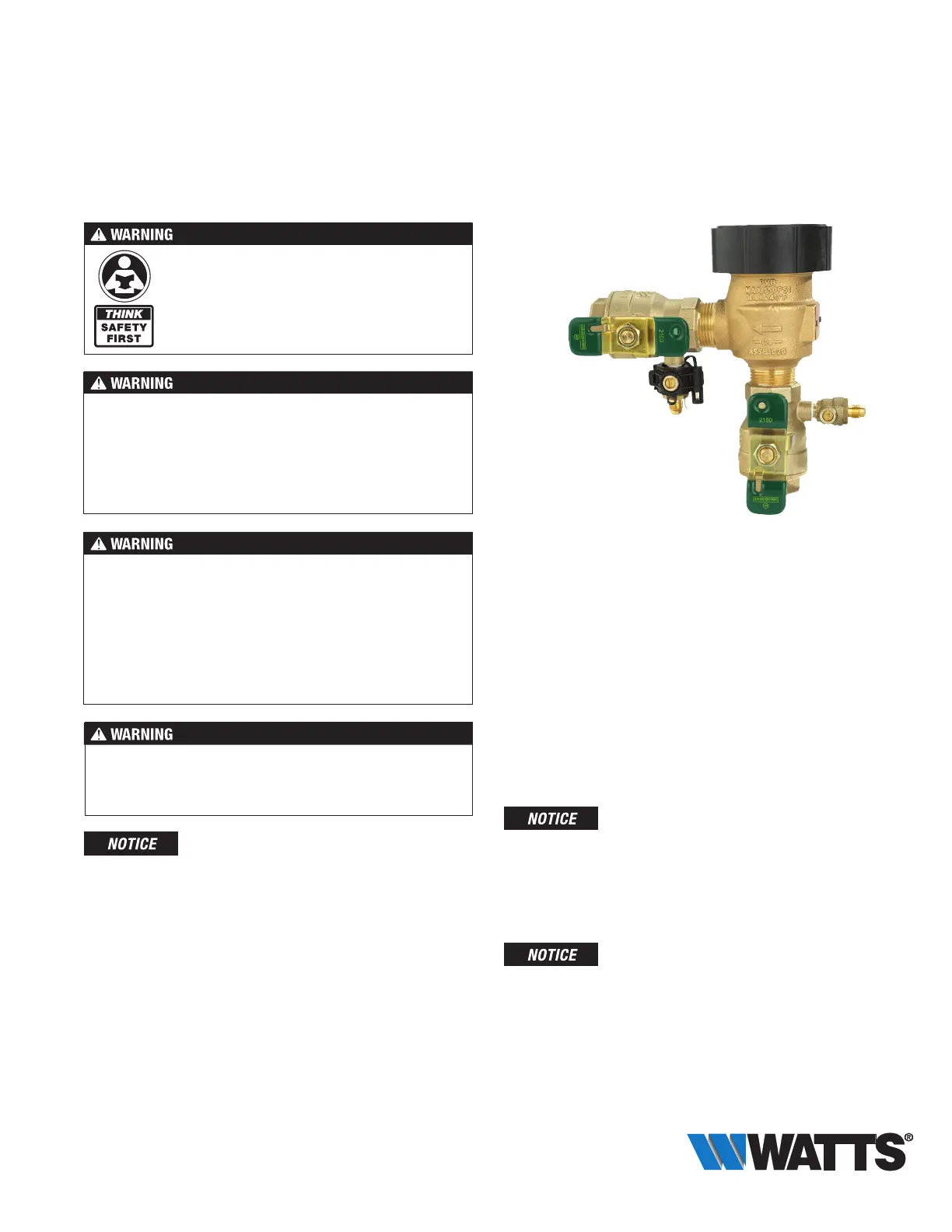
Series 800M4, LF800M4
Pressure Vacuum Breaker Assemblies
1
2" – 2"
Read this Manual BEFORE using this equipment.
Failure to read and follow all safety and use information
can result in death, serious personal injury, property
damage, or damage to the equipment.
Keep this Manual for future reference.
Local building or plumbing codes may require modifications
to the information provided. You are required to consult the
local building and plumbing codes prior to installation. If
the information provided here is not consistent with local
building or plumbing codes, the local codes should be
followed. This product must be installed by a licensed
contractor in accordance with local codes and ordinances.
Need for Periodic Inspection/Maintenance: This product
must be tested periodically in compliance with local codes,
but at least once per year or more as service conditions
warrant. All products must be retested once maintenance
has been performed. Corrosive water conditions and/or
unauthorized adjustments or repair could render the product
ineffective for the service intended. Regular checking and
cleaning of the product’s internal and external components
helps assure maximum life and proper product function.
Freeze sensor solely provides alerts about a possible freeze
event and cannot prevent a freeze event from occurring.
User action is required to prevent freeze conditions from
causing product and/or property damage.
For Australia and New Zealand, line strainers should be
installed between the upstream shutoff valve and the inlet of
the backflow preventer.
If installed on a fire sprinkler system, all mechanical checks,
such as alarm checks and backflow preventers, should be flow
tested and inspected internally in accordance with NFPA 13
and NFPA 25.
Testing
For field testing procedure, refer to Watts installation sheets
IS-TK-DL, IS-TK-9A, IS-TK-99D, and IS-TK-99E at
www.watts.com.
For other repair kits and service parts, refer to the Backflow
Prevention Products Repair Kits & Service Parts price list
PL-RP-BPD at www.watts.com.
For technical assistance contact your local Watts representative.
800M4FR-FZ
Series 800M4 and LF800M4 antisiphon PVBs (FR and QT
versions) are ideal for continuous pressure health hazard
applications where exposure to sudden freezing conditions may
occur, particularly in irrigation systems and industrial process
water systems.
Both series include a sensor for use with SentryPlus Alert
®
technology to monitor temperature and alert facility personnel when
freeze conditions can cause damage to equipment. (The sensor
is installed on the assembly exterior and does not alter assembly
functions or certifications.) The monitoring system is compatible
with BMS and irrigation management systems, allowing freeze
alerts to be distributed according to the BMS or IMS application.
When the monitoring system is Wi-Fi enabled, notifications can be
issued through the Smart Freeze Alert cloud service.
An add-on connection kit (sold separately) is required to activate
the freeze sensor. Without the connection kit, the sensor is
a passive component that has no communication with any
other device. (The kit can also be used to install an alternative
standalone outdoor sensor or to retrofit existing installations. See
“Add-on/Retrofit Sensor Connection Kit,” for ordering details.)
Use of the freeze sensor and activation kit with FZ models does
not replace the need to comply with all required instructions,
codes, and regulations related to installation, operation, and
maintenance of the PVB assembly.
Watts is not responsible for the failure of alerts due to connectivity
issues, power outages, or improper installation.
Installation Guidelines
Pressure — Temperature
Working Temperature 33°F to 140°F (0.5°C to 60°C)
Maximum Pressure 150 psi (10.3 bar)
Minimum Pressure 15 psi (103 kPa)
Requirements
Install 12" above the highest point of downstream piping.
(See Figure 1.)
Installation as stated above is essential for proper operation
Install bonnet side up and allow access for testing/service.
Install where discharge or spillage is not objectionable.
Do not undersize supply or oversize the valve relative to
demand.
Do not install where backpressure can occur.
Protect from freezing. For freeze protection, specify Model
800M4FR or LF800M4FR. Or, consider the WattsBox insu-
lated enclosure. For more information, download ES-WB at
www.watts.com.
Follow ASSE Standard 1020 that the atmospheric vent valve
remains open until the valve body pressure exceeds 1 lb. Until
this pressure is reached, some amount of spillage occurs at
the atmospheric vent. To minimize this leakage on start-up,
close the downstream shutoff valve and open the inlet shut-
off valve quickly.
Start-up Procedure
1. Close shutoff No. 2 (outlet).
2. Open shutoff No. 1 (inlet) until water discharges from the
bonnet then quickly open to pressurize the valve.
3. Open shutoff No. 2.
Freeze Protection
Use the following procedure to purge the PVB assembly with
pessurized air. (See Figure 2.)
1. Close the main shutoff valve.
2. Open upstream drain, test cocks and isolation ball valves to
depressurize line.
3. Purge with pressurized line.
4. Leave test cocks and isolation ball valve handles in 45°
angle to drain ball valves and prevent casting damage.
Typical Installation
The TWS hydrant is usually included in the PVB installation to
provide outside access to a building water supply for start-up,
winterizing, and servicing of irrigation sprinkler systems. (See
Figure 3.) The hydrant is connected to the PVB assembly and
installed through the structure wall to connect to the water
supply.
Figure 1
WattsBox
12" Minimum Clearance
Above the Highest Point of
Downstream Piping
Figure 2
Main Shutoff Valve
Flow
Union
Outlet Drain
Valve
Valve Pit
Sprinkler
System
Piping
12" Minimum Clearance
Above the Highest Point of
Downstream Piping
Upstream (Inlet) Drain
Figure 3
Key
Watts TWS
Drain Port or
Blow Down
Water
Supply
To Sprinklers
2


Produkt Specifikationer

Mærke: Watts
Kategori: Ikke kategoriseret
Model: 800M4-QT-FZ

Har du brug for hjælp?

Hvis du har brug for hjælp til Watts 800M4-QT-FZ stil et spørgsmål nedenfor, og andre brugere vil svare dig


Ikke kategoriseret Watts Manualer

Watts

Watts 800M4-QT-FZ Manual

17 September 2025
Watts

Watts LF7R10-U2 Manual

16 Juni 2025
Watts

Watts ETX-30 Manual

16 Juni 2025
Watts

Watts ETX-15 Manual

15 Juni 2025
Watts

Watts LF8B Manual

15 Juni 2025
Watts

Watts PLT-5 Manual

15 Juni 2025
Watts

Watts LF288A Manual

14 Juni 2025
Watts

Watts LF7RU2-U2 Manual

14 Juni 2025

Ikke kategoriseret Manualer

Nyeste Ikke kategoriseret Manualer

Vestil

Vestil TM-22-M Manual

17 September 2025
Vestil

Vestil LAD-MM-4-P-YL Manual

17 September 2025
Vestil

Vestil JDFT Manual

17 September 2025
Delfield

Delfield 204P Manual

17 September 2025
DeLOCK

DeLOCK 91005 Manual

17 September 2025
Vestil

Vestil PNU-2496 Manual

17 September 2025
ServIt

ServIt 423PSWELEM72 Manual

17 September 2025
Cambro

Cambro PCUPH615 Manual

17 September 2025
Kela

Kela Sinerio 22231 Manual

17 September 2025
Vestil

Vestil FTTM-2 Manual

17 September 2025