This document will guide you through the
basic installation process for your new D-Link
Industrial Ethernet Switch.
DIS-100E/G Series
Quick Installation Guide
Industrial Ethernet Switch
Documentation is also available
on the D-Link website
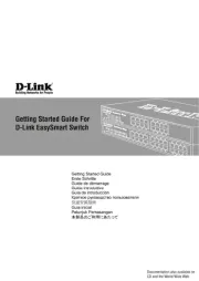
DIS-100G-06
Figure 2
# LED Status Description
1 Power
Solid Green Device power on
Light
O
Device power o
2 Port 1 - 4
Solid Green Secure 10/100/1000 Mbps connectivity
Blinking
Green
Transmitting/receiving data
Light
O
No connectivity
3 Port 5 - 6
Solid Green Secure 1000 Mbps connectivity
Blinking
Green
Transmitting/receiving data
Light
O
No connectivity
Before You Begin
The DIS-100E-05, DIS-100G-06, DIS-100G-06P and
DIS-100G-10 unmanaged Industrial Gigabit Ethernet
Switch solutions are designed for supporting
standard industrial applications without complex
setup to make the network truly plug-and-play.
Package Contents
This package should include the following items:
• DIS-100E/G switch
• DIN rail mounting kit
• DC power terminal block
• Quick installation guide
• SFP Connector Cover (Except DIS-100E-05)
If any of the above items are damaged or missing,
please contact your local D-Link reseller.
Hardware Overview
LED Indicators
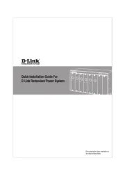
DIS-100E-05
2
1
Figure 1
# LED Status Description
1 Power
Solid Green Device power on
Light O Device power o
2 Port 1 - 5
Solid Green Secure 10/100 Mbps connectivity
Blinking
Green
Transmitting/receiving data
Light
O
No connectivity
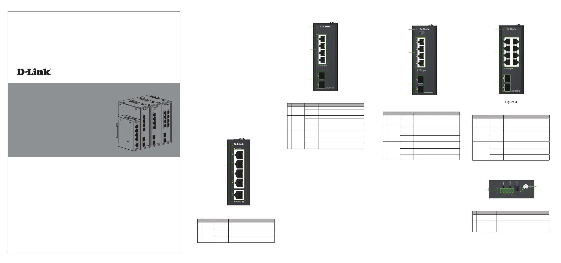
1
2
3
DIS-100G-10
Figure 4
# LED Status Description
1 Power
Solid Green Device power on
Light
O
Device power o
2 Port 1 - 8
Solid Green Secure 10/100/1000 Mbps connectivity
Blinking
Green
Transmitting/receiving data
Light
O
No connectivity
3 Port 9 - 10
Solid Green Secure 1000 Mbps connectivity
Blinking
Green
Transmitting/receiving data
Light
O
No connectivity
# LED Status Description
1 Power
Solid Green Device power on
Light
O
Device power o
2 Port 1 - 4
Solid Green Secure 10/100/1000 Mbps connectivity
Blinking
Green
Transmitting/receiving data
Solid Amber Transmitting power to powered device (PD)
Light
O
No connectivity
3 Port 5 - 6
Solid Green Secure 1000 Mbps connectivity
Blinking
Green
Transmitting/receiving data
Light
O
No connectivity
1
2
3
Top Panel Connectors
Figure 5
# Connector Description
1 Terminal Block
Input Used to connect the switch to external
power adapter
2 Switch Ground Used to ground the switch
3 Power Input
Input Used to connect the switch to external
power adapter. This only for system. Doesn’t
support PoE function.
1
2
3
DIS-100G-06P
Figure 3
1
2
3