PL
DE
RUS
GB
RO
CZ
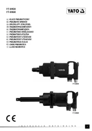
KLUCZ DYNAMOMETRYCZNY
TORQUE SPANNER
LAGERABZIEHVORRICHTUNG
ДИНАМОМЕТРИЧЕСКИЙ КЛЮЧ
DYNAMOMETRICKÝ KLÍČ
CHEIE TENSIOMETRICĂ
item number:
YT-0750
item number:
YT-0760
item number:
YT-0761
item number:
YT-0767
item number:
YT-0770
PL
DE
RUS
GB
RO
CZ
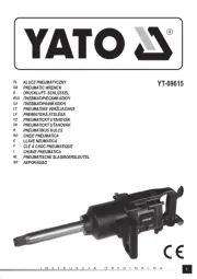
WZMACNIACZ MOMENTU OBROTOWEGO
TORQUE MULTIPLIER
LAGERABZIEHVORRICHTUNG
УСИЛИТЕЛЬ ВРАЩАЮЩЕГО МОМЕНТА
POSILOVAČ KROUTICÍHO MOMENTU
MULTIPLICATORULUI DE TORSIUNE
item number:
YT-0780
item number:
YT-0781
PL
CHARAKTERYSTYKA NARZĘDZIA
Klucz dynamometryczny jest precyzyjnym instrumentem stosowanym do uzyskiwania określonego momentu obrotowego. Służy
do skręcania części złącznych gwintowanych tak, aby moment obrotowy połączenia był znany i odpowiedni do rodzaju materiału i
wytrzymałości śruby i nakrętki.
Zestawienie porównawcze momentów w różnych jednostkach długości i siły:
1 kG*cm = 13,887 OZ*IN (uncja x cal)
1 kG*cm = 0,867 LB*IN (funt x cal)
1kG*m = 9,80665 N*m (Niuton x metr)
1 kG*m = 7,233 LB*FT (funt x stopa)
1FT*LB = 12 LB*IN (funt x cal)
1dm*N = 14,16 OZ*IN (uncja x cal)
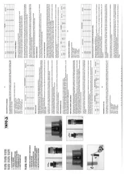
Indeks Rozmiar zabieraka
Moment obrotowy [Nm]
Długość [mm]
Min. Max.
YT-0750 3/8” 19 110 366
YT-0760 1/2” 42 210 470
YT-0761 1/2” 40 210 535
YT-0770 3/4” 100 500 865
YT-0771 3/4” 140 980 1230
YT-0767 1/2” 40 210 505
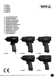
OBSŁUGA KLUCZA
Wybrać odpowiednią skalę Nm lub in-lbs. Odblokować pokrętło mikrometryczne (I).
Pokrętło mikrometryczne ustawić tak, aby „0” na skali pokrętła pokryło się z pionową linią na ramieniu klucza (II).
Pokrętło mikrometryczne obracać zgodnie z kierunkiem ruchu wskazówek zegara, do momentu ustawienia żądanego momentu ob-
rotowego. Żądany moment obrotowy jest ustawiony w momencie, gdy podziałka na pokrętle mikrometrycznym będzie się pokrywała
z pionową linią na ramieniu klucza. (III)
Następnie należy zablokować pokrętło mikrometryczne (IV) oraz ustawić odpowiedni kierunek obrotu grzechotki, po tym klucz jest
gotowy do użytku.
Na zabierak klucza należy nałożyć odpowiednią nasadkę. Podczas dokręcania osiągnięcie ustawionego momentu jest sygnalizo-
wane kliknięciem klucza. W przypadku usłyszenia lub wyczucia kliknięcia należy zaprzestać dokręcania.
Uwaga! Nie wolno kontynuować dokręcania śrub po tym jak klucz zasygnalizuje nastawiony moment obrotowy. Należy na to zwrócić
szczególną uwagę podczas dokręcania z niewielkimi momentami.
Nie wolno nastawiać wartości momentu spoza zakresu pomiarowego klucza.
Uwaga! Nie wolno stosować, żadnych przedłużeń klucza, w celu wydłużenia ramienia, do którego przykładana jest siła. Na przykład
przez zastosowanie dodatkowej rury przedłużającej.
PRZECHOWYWANIE KLUCZA
Jeśli klucz nie będzie używany przez dłuższy czas należy nastawić minimalny zakres.
Nie należy wykręcać pokrętła mikrometrycznego poniżej nastawy najniższego momentu.
Klucz wolno czyścić jedynie sucha miękka bawełnianą szmatką. Nie wolno używać jakichkolwiek rozpuszczalników, czy innych
cieczy. Gdyż mogą one wypłukać smar, którym fabrycznie jest nasmarowany mechanizm klucza.
Klucz jest wykalibrowany fabrycznie z dokładnością do 4%.
WZMACNIACZ MOMENTU OBROTOWEGO
Wzmacniacz momentu obrotowego jest narzędziem umożliwiającym osiąganie momentów obrotowych za pomocą klucza dynamo-
metrycznego fabrycznie nieprzystosowanego do osiągania takich wartości momentu. Jest to możliwe dzięki przekładni planetarnej,
zamontowanej w głowicy wzmacniacza momentu.
Zasada działania wzmacniacza momentu obrotowego polega na tym, że ramie wzmacniacza należy zaprzeć o nieruchomy obiekt,
o odpowiednio dużej wytrzymałości. Ramię wzmacniacza obraca się przeciwnie w stosunku do obrotu klucza.
W głowicy wzmacniacza występują 10% - 20% straty wartości momentu obrotowego, należy je uwzględnić w przypadku ustawiania
momentu obrotowego na kluczu dynamometrycznym.
Uwaga! Nie wolno przekraczać wartości maksymalnych momentów obrotowych wzmacniacza momentu. Może to doprowadzić do
zniszczenia zarówno klucza jak i wzmacniacza. Przeciążony wzmacniacz może nagle zwolnić stawiany opór, co może doprowadzić
do obrażeń.
Wzmacniacz momentu nie jest przystosowany do pracy z urządzeniami udarowymi. Praca przy wysokich udarowych obciążeniach
może doprowadzić do zniszczenia wzmacniacza.
Wzmacniacz momentu wolno czyścić jedynie suchą, miękką bawełnianą szmatką. Nie wolno używać jakichkolwiek rozpuszczalni-
ków, czy innych cieczy. Gdyż mogą one wypłukać smar, którym fabrycznie jest nasmarowany mechanizm klucza.
Indeks
Wymiar zabieraka Moment obrotowy [Nm]
Przekładnia Długość [mm]
Wejściowy Wyjściowy Wejściowy Wyjściowy
YT-0780 1/2” F 3/4” M 460 1400 3/1 420
YT-0781 3/4” F 1” M 900 2700 3/1 500
PROPERTIES OF THE TOOL
The torque spanner is a precise tool setting the torque. It has been designed to integrate threaded connecting elements in such a
manner that the torque of connection be known and appropriate for the kind of material and the strength of the screw and the nut.
Conversion of various torque unit of measure:
1 kG*cm = 13,887 OZ*IN
1 kG*cm = 0,867 LB*IN
1kG*m = 9,80665 N*m
1 kG*m = 7,233 LB*FT
1FT*LB = 12 LB*IN
1dm*N = 14,16 OZ*IN
Item no. Driver
Torque [Nm]
Length [mm]
Min. Max
YT-0750 3/8” 19 110 366
YT-0760 ½” 42 210 470
YT-0761 ½” 40 210 535
YT-0770 3/4” 100 500 865
YT-0771 3/4” 140 980 1230
YT-0767 ½” 40 210 505
OPERATIONAL OF TORQUE WRENCH
Choose the scale Nm or in-lbs. Unlock the torque wrench (I)
Turn the upper edge of adjusting handle to the reading “0” on the handle must align with the centerline of scale (II).
Then turn clockwise to align the wanted torque on the adjusting handle with the centerline of scale (III).
Soon as the required torque value is selected, set the fi xing button (fi xing casing) at LOCK position (IV).
After installing appropriate casing and fi xing on the work piece, apply force on the handle of torque wrench and then stop applying
force upon hearing “click” sound and at this time, the torque wrench will return to zero reset. Special attention should be paid when
using lower torque for setting, i.e. it is necessary to stop applying force soon as reaching the preset torque.
Caution: After the fi rst using or being left unused for longer time and it is required to use once again, be sure to use higher torque
to operate for 5-10 times so that the components within may be fully lubricated by the special-purpose lubricant oil. When it is not
used, be sure to set the torque to the lowest value.
Do not keep applying pressure after reaching the preset torque; otherwise, the work piece may get damaged.
Before setting the torque value, check to see if the torque wrench is at LOCK or UNLOCK status.
WRENCH MAINTENANCE
Upon the ex-factory, the torque wrench has been calibrated and tested in providing accuracy as high as ± 4%. As such, it belongs to
a kind of high-precision measuring instrument and only the well-trained professional can perform the service.
Do not soak in any liquid to avoid affecting the lubrication inside.
USE OF THE TORQUE MULTIPLIER
The mechanical advantage in the use of your torque multiplier is derived from the planetary transmission within the gear head of the
tool. With the torque multiplier reaction bar in a fi xed position against a stationary object, and the input tool driving, the socket and
fastener sees forces equaling the ratio of the torque multiplier or combination of multipliers being used times the input force. Due to
frictional losses in the gear train, a torque loss factor of 10% to 20% should be anticipated.
In breaking a diffi cult or frozen fastener, the driving force is simple reversed, it is important to set the reaction bar against a strong
stationary object. The reaction bar rotation is opposite the output force rotation. See sketch.
Caution: Do not exceed the rated capacity of the model torque multiplier being used. Excessive input force may result in tool failure
and sudden release of input drive.
Torque multipliers are not intended for use with input forces from impact tools. High shock loads may cause damage to tool.
Item no.
Driver Torque [Nm]
Output / Input Length [mm]
Input Output Input Output
YT-0780 1/2” F 3/4” M 460 1400 3/1 420
YT-0781 3/4” F 1” M 900 2700 3/1 500
DE
GB
CHARAKTERISTIK DES WERKZEUGS
Stellen Sie das Drehmoment wie folgt:
1 kG*cm = 13,887 OZ*IN
1 kG*cm = 0,867 LB*IN
1kG*m = 9,80665 N*m
1 kG*m = 7,233 LB*FT
1FT*LB = 12 LB*IN
1dm*N = 14,16 OZ*IN
No. Antrieb Nengrösse
Drehmoment [Nm]
Länge [mm]
Min. Max
YT-0750 3/8” 19 110 366
YT-0760 1/2” 42 210 470
YT-0761 1/2” 40 210 535
YT-0770 3/4” 100 500 865
YT-0771 3/4” 140 980 1230
YT-0767 1/2” 40 210 505
BEDIENUNGSANLEITUNG FÜR DREHMOMENT-SCHRAUBENSCHLÜSSEL
Setzen Sie das Fixiergehäuse auf ENTRIEGELN (I).
Um 80 Nm ein zustellen, drehen Sie die obere Kante des Einstellgriffs auf 80 Nm, wobei die Ablesung „0“ auf dem Griff senkrecht
mit der Mittellinie der Skalierung ausgerichtet sein muss (II).
Drehen Sie dann den Griff nach rechts (Uhrzeigersinn), um die Ablesung „4“ auf dem Einstellgriff senkrecht mit der Mittellinie der
Skalierung auszurichten, um 84 Nm zu erhalten (III).
Obald der gewünschte Drehmomentwert eingestellt ist, setzen Sie den Fixierknopf (Fixiergehäuse) auf VERRIEGELN, wie in (IV)
dargestellt ist.
Nach Installation der passenden Verkleidung und Fixierung am Werkstück üben Sie solange Druck auf den Griff des Drehmo-
ment-Schraubenschlüssels aus, bis Sie einen „Klickten“ hören, wobei sich dann der Drehmoment-Schraubenschlüssel auf Null
zurücksetzt.
Besondere Vorsicht ist geboten, wenn Sie ein niedrigeres Drehmoment eingestellt haben, nämlich, bei Erreichen des Voreingestell-
ten Drehmoments darf kein Druck mehr ausgeübt werden.
Achtung: Bei erstmaliger Benutzung oder nach einer längeren Benutzungspause müssen Sie 5-10 Mal ein höheres Drehmoment
einstellen, damit die inneren Komponenten vom Spezialschmieröl ganz eingefettet werden. Vor dem Wegstellen des Werkzeugs
müssen Sie das niedrigste Drehmoment einstellen.
Nach Erreichen des Voreingestellten Drehmoments dürfen Sie keinen Druck mehr ausüben; andernfalls wird das Werkstück be-
schädigt.
INSTRUKC JA OBSŁ UGI
item number:
YT-0771
I
II
III
IV
V