Zurn Z1186-ST Manual
Zurn
Ikke kategoriseret
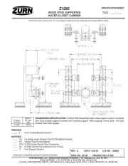
Z1186-ST

| Mærke: | Zurn |
| Kategori: | Ikke kategoriseret |
| Model: | Z1186-ST |
Har du brug for hjælp?
Hvis du har brug for hjælp til Zurn Z1186-ST stil et spørgsmål nedenfor, og andre brugere vil svare dig
Ikke kategoriseret Zurn Manualer

10 December 2025

9 December 2025

9 December 2025

3 December 2025

3 December 2025

3 December 2025

3 December 2025

3 December 2025

3 December 2025
12 November 2025
Ikke kategoriseret Manualer
- Airlive
- HTW
- Eonon
- Ednet
- First Alert
- Louis Tellier
- Primera
- Tech 21
- Cudy
- Vestil
- Code Mercenaries
- Cleco
- Gaslock
- Elation
- Milectric
Nyeste Ikke kategoriseret Manualer

10 December 2025

10 December 2025

10 December 2025

10 December 2025

10 December 2025

10 December 2025

10 December 2025

10 December 2025

10 December 2025

10 December 2025