ZZ-2 ZW-GMLCv2 Manual
ZZ-2
Ikke kategoriseret
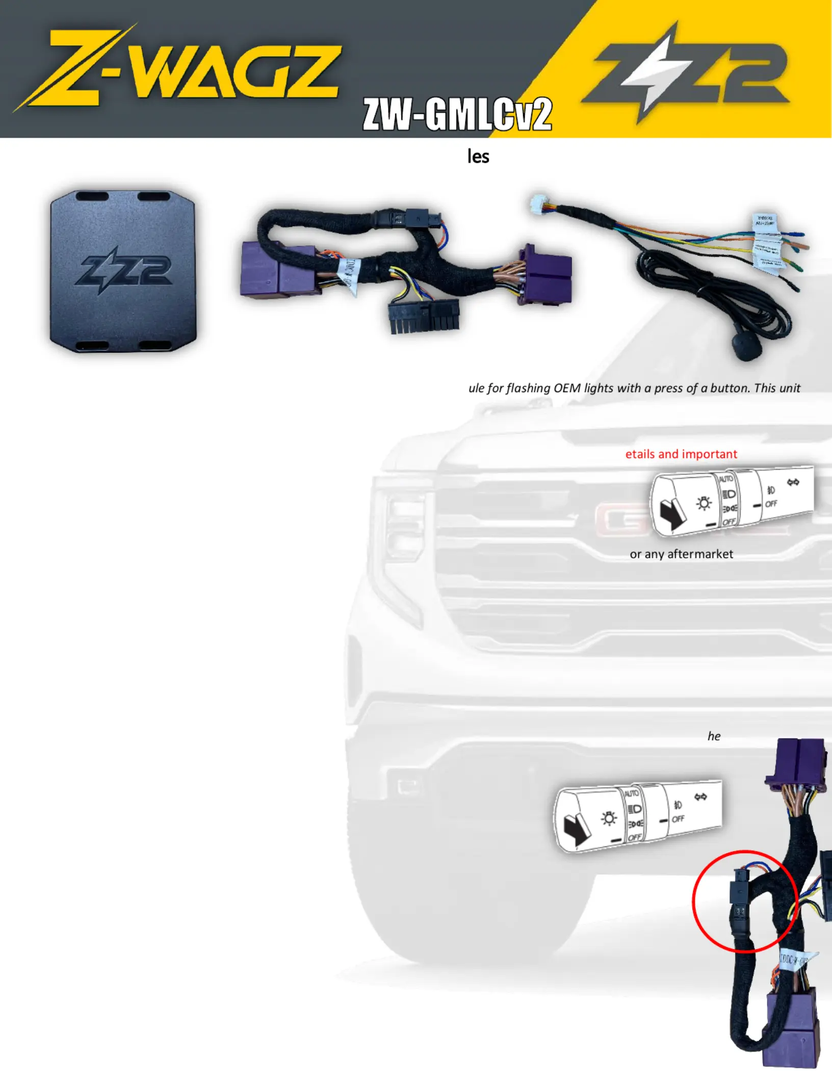
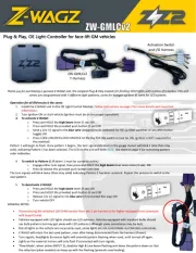
ZW-GMLCv2
| Mærke: | ZZ-2 |
| Kategori: | Ikke kategoriseret |
| Model: | ZW-GMLCv2 |
Har du brug for hjælp?
Hvis du har brug for hjælp til ZZ-2 ZW-GMLCv2 stil et spørgsmål nedenfor, og andre brugere vil svare dig
Ikke kategoriseret ZZ-2 Manualer
26 August 2025
Ikke kategoriseret Manualer
- Küppersbusch
- WOOOD
- Medel
- Evga
- SKS
- Crown
- Abus
- Epcom
- Frigidaire
- MILESEEY
- Indesit
- Yeastar
- Lupine
- Mermade Hair
- Lowrance
Nyeste Ikke kategoriseret Manualer

10 Januar 2026

10 Januar 2026

10 Januar 2026

10 Januar 2026

10 Januar 2026

10 Januar 2026

10 Januar 2026

10 Januar 2026

10 Januar 2026

10 Januar 2026