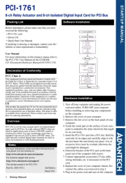
Advantech PCI-1761 Manual

Advantech PCI-kort PCI-1761

Læs gratis den danske manual til Advantech PCI-1761 (2 sider) i kategorien PCI-kort. Denne vejledning er vurderet som hjælpsom af 2 personer og har en gennemsnitlig bedømmelse på 4.9 stjerner ud af 1.5 anmeldelser. Har du et spørgsmål om Advantech PCI-1761, eller vil du spørge andre brugere om produktet?

Side 1/2
1 Startup Manual
STARTUP MANUAL
PCI-1761
8-ch Relay Actuator and 8-ch Isolated Digital Input Card for PCI Bus
Before installation, please make sure that you have
received the following:
• PCI-1761 card
• Driver CD
If anything is missing or damaged, contact your dis-
tributor or sales representative immediately.
User Manual
For more information on this product, please refer to
the PCI-1761 User Manual on the CD-ROM:
CD:\Documents\Hardware Manuals\PCI\PCI-1761
FCC Class A
This equipment has been tested and found to comply with
the limits for a Class A digital device, pursuant to part 15 of
the FCC Rules. These limits are designed to provide reason-
able protection against harmful interference when the equip-
ment is operated in a commercial environment. This
equipment generates, uses, and can radiate radio frequency
energy and, if not installed and used in accordance with the
instruction manual, may cause harmful interference to radio
communications. Operation of this equipment in a residen-
tial area is likely to cause interference in which case the user
is required to correct interference at his own expense.
CE
This product has passed the CE test for environmental speci-
fications when shielded cables are used for external wiring.
We recommend the use of shielded cables. This kind of cable
is available from Advantech. Please contact your local sup-
plier for ordering information.
PCI-1761 is a 8-ch relay actuator and 8-ch isolated digital
input card for PCI bus. Its eight onboard SPDT relays are
ideal for applications such as device ON/OFF control or
small power switch. For easy monitoring, each relay is
equipped with one red LED to show ON/OFF status. The
eight optically-isolated digital input channels are ideal in
noisy environments or with floating potential.
1. Turn off your computer and unplug the power
cord and cables. TURN OFF your computer
before installing or removing any components
on the computer.
2. Remove the cover of your computer.
3. Remove the slot cover on the back panel of your
computer.
4. Touch the metal part on the surface of your com-
puter to neutralize the static electricity that might
be on your body.
5. Insert the PCI-1761 card into a PCI slot. Hold the
card only by its edges and carefully align it with
the slot.Insert the card firmly into place. Use of
excessive force must be avoided, otherwise the
card might be damaged.
6. Fasten the bracket of the PCI card on the back
panel rail of the computer with screws.
7. Connect appropriate accessories (37-pin cable,
wiring terminals, etc. if necessary) to the PCI
card.
8. Replace the cover of your computer chassis. Re-
connect the cables you removed in step 2.
9. Plug in the power cord and turn on the computer.
Packing List Software Installation
Declaration of Conformity
Overview
Notes
For more information on this and other Advantech prod-
ucts, please visit our websites at:
http://www.advantech.com/eAutomation
For technical support and service:
http://www.advantech.com/support/
This startup manual is for PCI-1761
Part No. 2003176111 2nd Edition
March 2011
Hardware Installation
2 Startup Manual
Pin Assignments
Isolated Digital Input Connections
The PCI-1761 has 8 isolated digital input channels des-
ignated IDI0~IDI7. Each of isolated digital input chan-
nel accepts 10~50 V
DC
voltage inputs, and accept bi-
directional input. It means that you can apply positive or
negative voltage to an isolated input pin (Vin). The fig-
ure below shows how to connect an external input
source to one of the card’s input channels.
Relay Connections
After power on, the initial relay output status of PCI-
1761 is shown as below:
A write operation to I/O address, BASE +0, will change
the output status of each relay. For example, if Bit 0 of
BASE +0 is set 1” (logic high), relay 0, K0, will switch
from position “NORMALLY CLOSED”, R0_NC, to
position “NORMALLY OPEN”, R0_NO. This means
that LOAD2 will be de-energized, while LOAD1 is
energized. To summarize, the “COMMON” line con-
nect to the “NORMALLY CLOSED” line, if the corre-
sponding bit is set as 0 (power-on initial status).
Otherwise, if the corresponding bit is set as 1, then the
“COMMON” line will connect to the “NORMALLY
OPEN” line.
Pin Assignments
Signal Connections


Produkt Specifikationer

Mærke: Advantech
Kategori: PCI-kort
Model: PCI-1761

Har du brug for hjælp?

Hvis du har brug for hjælp til Advantech PCI-1761 stil et spørgsmål nedenfor, og andre brugere vil svare dig


PCI-kort Advantech Manualer

PCI-kort Manualer

Nyeste PCI-kort Manualer