Advantech USB-5817 Manual


Læs gratis den danske manual til Advantech USB-5817 (3 sider) i kategorien Ikke kategoriseret. Denne vejledning er vurderet som hjælpsom af 3 personer og har en gennemsnitlig bedømmelse på 4.5 stjerner ud af 2 anmeldelser. Har du et spørgsmål om Advantech USB-5817, eller vil du spørge andre brugere om produktet?

Side 1/3
USB-5817 Startup Manual 1
Before installation, please ensure that the following items
are included with the product:
1. 1 x USB-5817 module
2. 4 x Terminal blocks
3. 1 x Startup manual
4. 1 x USB 3.0 lockable cable (1 m)
If any of the above items are missing or damaged, contact
your distributor or sales representative immediately.
For more detailed information regarding this product, please
download the USB-5817 user manual from the Advantech
website.
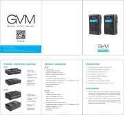
Advantech’s USB-5817 is an industrial USB 3.0 isolated
analog input module. To ensure easy installation in cabinet
computers, USB-5817 modules are compact and equipped
with a DIN rail mount kit. The built-in USB hub can support
a daisy-chain topology, while Euro-type pluggable terminal
blocks and LED indicators facilitate conguration and
maintenance.
USB-5817
8-Channel,16-Bit, 200 kS/s USB 3.0 Isolated
Analog Input Module
Startup Manual
General
• Connectors:
- 2 x 10-pin terminal block (3.81 mm, AI)
- 2 x 3-pin screw terminal block (3.81 mm, power)
- USB 3.0 type A (downstream port)
- USB 3.0 type B (upstream port)
• Dimensions:
120 x 120 x 40 mm
3
(4.72 x 4.72 x 1.57 in
3
)
• OperatingTemperature: 0 ~ 60 °C (32 ~ 140 °F)
• StorageTemperature:-40 ~ 70 °C (-40 ~ 158 °F)
• StorageHumidity:5 ~ 95% RH (non-condensing)
• PowerSupply:10 ~ 30 V
DC
• Interface: USB 3.0
• DataTransferRates: 5 Gbps
• PowerConsumption:
- Using USB bus power: 350 mA typical @ 5 V
- Using external power: 100 mA typical @ 24 V
• ESDProtection
- Air: ±8 kV
- Contact: ±6 kV
• DCSurgeProtection: 2 kV
AnalogInput
• NumberofInputChannels:8 differential, can be en-
abled/disabled independently using software
• A/DConverter(ADC)Resolution:16 bits (15 bits for
current measurement)
• A/DConverter(ADC)Type:Successive approximation
(SAR)
• MaximumSampleRates(fs):200 kS/s shared by all
channels
• InputCoupling:DC
• InputRange:±10 V, 0 ~ 20 mA
• InputCommon-ModeVoltageRange:±275 V
• AbsoluteAccuracy
-OffsetError:< ±1 mV
- GainError:< ±0.01% of full-scale range
• TemperatureDrift
-OffsetDrift:25 ppm/°C
- GainDrift:15 ppm/°C
• Bandwidth(-3dB):10 kHz
• IdleChannelNoise:0.27 mV
RMS
(16 bits effective resolu-
tion)
• Signal-to-NoiseRatio(SNR):87 dB
• TotalHarmonicDistortion(THD):-98 dB
• TotalHarmonicDistortionPlusNoise(THD+N):-87 dB
• Spurious-FreeDynamicRange(SFDR):102 dB
• EffectiveNumberofBits(ENOB):14.2 bits
PackingList
For more information about this or other Advantech
products, please visit our website at
http://www.advantech.com
For driver/SDK downloads and technical support
services, please visit our support website at
http://support.advantech.com
This manual is for USB-5817.
Part No. 2041581700
Printed in China
Edition 1
January 2019
Specications
Overview
UserManual
2 USB-5817 Startup Manual
USB-5817 modules have a built-in DIP switch that is used
to dene the board ID for each module. When multiple
modules are installed in the same system, the board
ID switch can be used to identify each module’s device
number. Every module in the system should be assigned
different device numbers. The default board ID value is 0.
When conguring the board ID to any other value, refer to
the settings in the following table:
Switches
SW2~SW8 are used to congure the analog input as volt-
age measurement (±10 V) or current measurement (0 ~ 20
mA). The default setting is voltage measurement.
• InputImpedance
- Differential:800 kΩ
- CommonMode:200 kΩ
• InputFIFOSize:4,096 samples shared among all
enabled channels
1. Install the SDK and drivers downloaded from the
Advantech website.
2. Touch the metal case of the computer to discharge any
static electricity that may be in your body.
3. Insert the USB module into the designated USB port.
Use caution when inserting the module to avoid damag-
ing the components from excessive force.
FCCClassA
This equipment has been tested and found to comply with
the limits for a Class A digital device, pursuant to part 15
of the FCC rules. These limits are designed to provide rea-
sonable protection against harmful interference when the
equipment is operated in a commercial environment. This
equipment generates, uses, and can radiate radio frequen-
cy energy and, if not installed and operated in accordance
with the instruction manual, may cause harmful interference
to radio communications. Operation of this equipment in
a residential area is likely to cause interference. In such
cases, users are required to correct the interference at their
own expense.
CE
This product has passed the CE test for environmental
specications when shielded cables are used for external
wiring. We recommend the use of shielded cables. Such
cables are available from Advantech. Please contact your
local supplier for ordering information.
USB-5817 modules feature two power input terminals with
an input power range of 10 ~ 30 V
DC
and power redun-
dancy support. For modules connected to two power input
sources, if one source is inactive or interrupted, the other
power source can immediately assume supply operations.
Accordingly, USB-5817 modules can operate with a single
power source. (The modules can also be powered via USB
if there is no device connected to the downstream port.)
BoardIDSwitch
DeclarationofConformity
Specications(Cont.)
Power
InstallationInstructions


Produkt Specifikationer

Mærke: Advantech
Kategori: Ikke kategoriseret
Model: USB-5817

Har du brug for hjælp?

Hvis du har brug for hjælp til Advantech USB-5817 stil et spørgsmål nedenfor, og andre brugere vil svare dig