AMX AXB-IRS4 Manual
| Mærke: | AMX |
| Kategori: | Joystick |
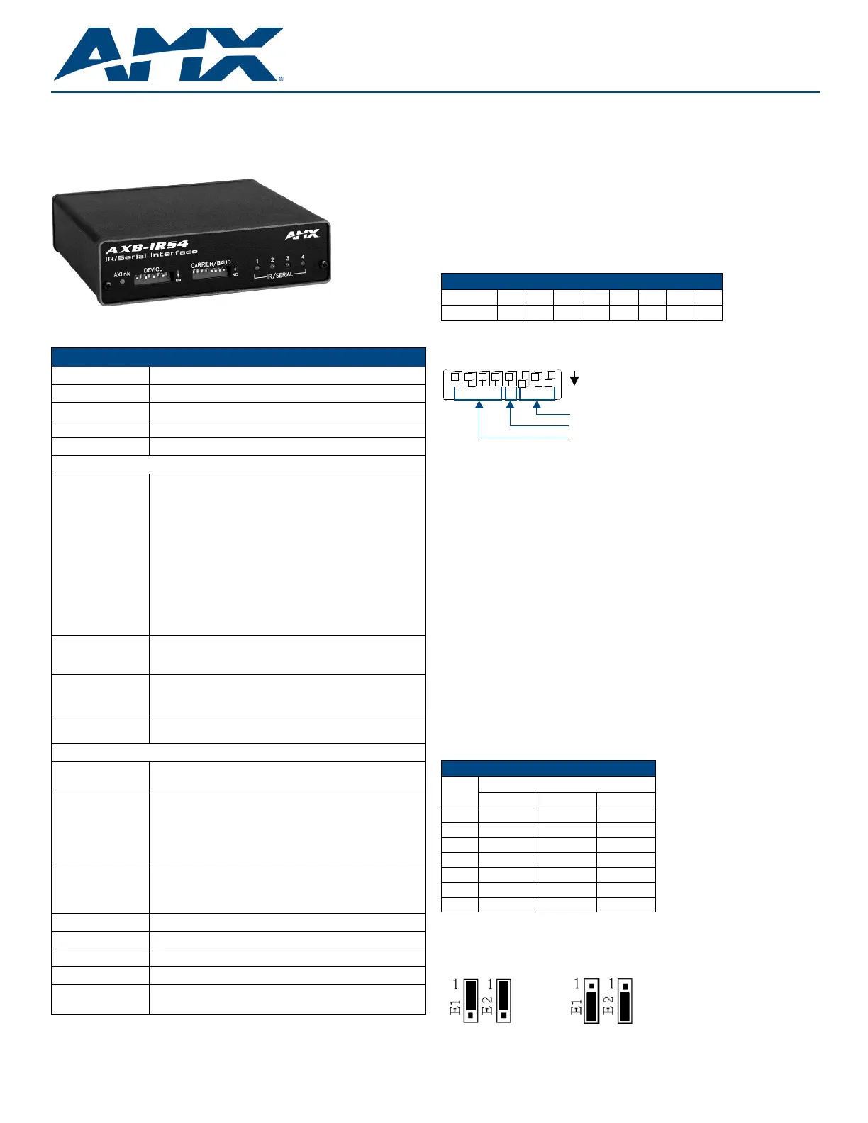
| Model: | AXB-IRS4 |
Har du brug for hjælp?
Hvis du har brug for hjælp til AMX AXB-IRS4 stil et spørgsmål nedenfor, og andre brugere vil svare dig
Joystick AMX Manualer
15 September 2025
14 September 2025

14 September 2025
14 September 2025
14 September 2025
14 September 2025
14 September 2025
14 September 2025
14 September 2025
14 September 2025
Joystick Manualer
- Allied Telesis
- Genesis
- Rain Bird
- Wireless Solution
- Speedlink
- Sirius
- Pyle
- Movistar
- Hori
- Mackie
- Korg
- Carat
- Redragon
- Metronic
- Belkin
Nyeste Joystick Manualer

20 December 2025

20 December 2025

10 December 2025

7 December 2025

28 November 2025

27 November 2025

20 November 2025

19 November 2025

18 November 2025

17 November 2025