Aruba AP-515 Manual


Læs gratis den danske manual til Aruba AP-515 (15 sider) i kategorien Adgangspunkt. Denne vejledning er vurderet som hjælpsom af 19 personer og har en gennemsnitlig bedømmelse på 4.7 stjerner ud af 10 anmeldelser. Har du et spørgsmål om Aruba AP-515, eller vil du spørge andre brugere om produktet?

Side 1/15
Aruba 510 Series Campus Access Points
Installation Guide
Rev05 | December 2019 1
The Aruba 510 Series Campus Access Points (AP-514 and AP-515) are high-performance, multi-radio wireless
devices that can be deployed in either controller-based (ArubaOS) or controllerless (Aruba Instant) network
environments. These access points deliver high performance concurrent 2.4 GHz and 5 GHz 802.11ax Wi-Fi
functionality with MIMO radios (2x2 in 2.4 GHz, 4x4 in 5 GHz), while also supporting legacy 802.11a/b/g/n/ac
wireless services.
Ethernet ports located on the back of this access points are used to connect the device to the wired networking
infrastructure and to provide (802.3at class 4) PoE power to the device.
In addition to both Wi-Fi radios, these APs also incorporate a Bluetooth Low Energy (BLE) and Zigbee radio,
supporting a variety of use-cases and services, such as locationing and IoT.
A mount kit (sold separately) is needed to mount the AP. Make sure to purchase the correct mount kit for the
intended deployment of the AP.
Package Contents
Aruba 510 Series Campus Access Point (with a pre-installed mount bracket)
Hardware Overview
The following sections outline the hardware components of the 510 Series access points.
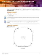
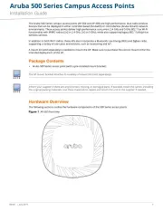
Figure 1 AP-515 Front View
The AP mount bracket attaches to a variety of mount kits (sold separately).
Inform your supplier if there are any incorrect, missing, or damaged parts. If possible,
retain the carton, including
the original packing materials. Use these materials to repack and return the unit to the supplier if needed.
2Aruba 510 Series Campus Access Points | Installation Guide
Figure 2 LEDs (AP-515 shown)
Figure 3 AP-514 Front View
External Antenna Connectors
The AP-514 access points are equipped with four external antenna connectors located on the front
corners of the access point (see
Figure 3
). Antenna ports A0 and A1 (co
rresponding with radio chains 0
and 1), are used for both radios and bands (RF signals are diplexed), while antenna ports A2 and A3
(corresponding with radio chains 2 and 3) are used for the 5 GHz radio only.
A0
A1
A2
A3


Produkt Specifikationer

Mærke: Aruba
Kategori: Adgangspunkt
Model: AP-515

Har du brug for hjælp?

Hvis du har brug for hjælp til Aruba AP-515 stil et spørgsmål nedenfor, og andre brugere vil svare dig